
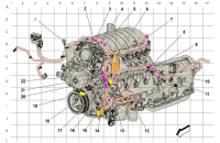
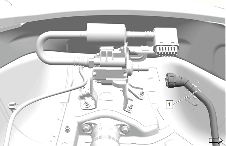
When diagnosing engine performance issues, DTCs P0340 (Intake/Single Camshaft Position Sensor Circuit), P0341 (Intake/Single Camshaft Position Sensor Performance), P0011 (Intake/Single Camshaft Position System Performance) or P0016 (Crankshaft Position Sensor and Intake/Single Camshaft Position Sensor Correlation) may be set in the Engine Control Module (ECM), depending on the engine application, leading to further inspection of the camshaft position sensors (CMP). (Fig. 11)
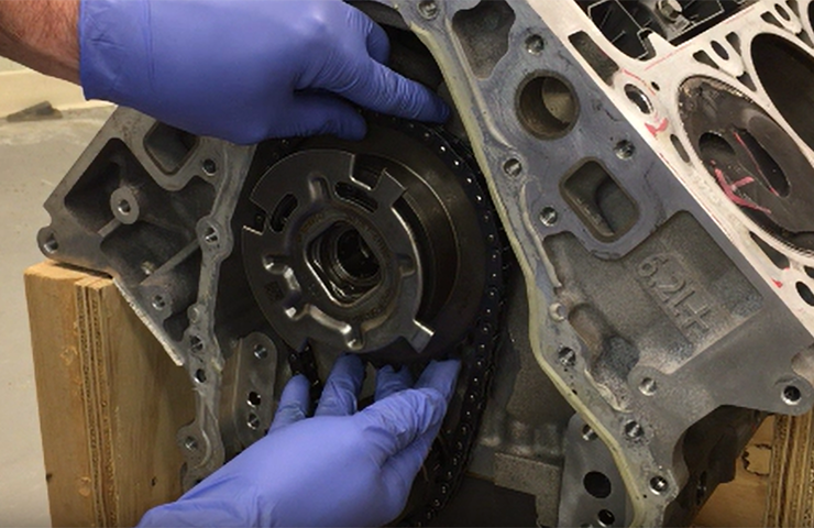
Fig. 11
The CMP contains a hall-effect sensor and additional electronics that processes the signal. It detects the change of strength of the magnetic field caused by the reluctor ring. There are 4 teeth on the edge of the camshaft position reluctor ring mounted on the camshaft. When the strength changes, the sensor changes the amount of current it consumes. This results in a square wave signal of current and voltage. The control module detects the frequency in which the signal changes, which is proportional to the rotational speed.
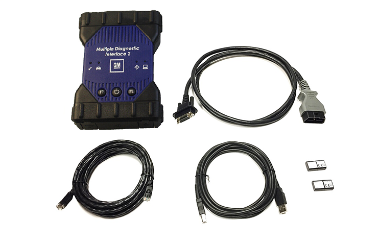
To help with diagnosis, the PicoScope can be used to evaluate the CMP sensors. The GM Technical Assistance Center (TAC) has seen an increase in sensor, circuit and ECM replacement due to DTCs P0340/341 and P0011/0016 without checking a scope pattern of the actuator interrupter ring. Comparing the wave form of a possibly damaged actuator ring with a known good wave form can speed up diagnosis due to the time and labor involved with engine disassembly as well as reduce unnecessary parts replacement.
Compare Wave Patterns
Following is a good wave form (CMP/VVT). (Fig. 12)
- Red is sensor off time, or 0V.
- Green is on time, or at 5v.
- Noise in the signal, underlined in yellow, is normal and does not affect ECM interpretation of the signal.
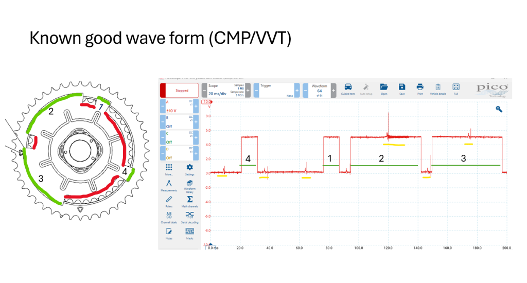
Fig. 12
Following is a bad wave form pattern. (Fig. 13).
The filled-in rectangular shapes are the parts of the pattern missing due to bent or damaged interrupter blades.
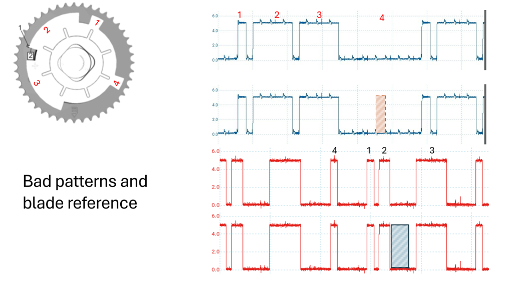
Fig. 13
Check for Actuator Damage
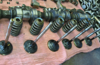
Damage to reluctor rings can be seen easily with the actuator placed on a flat work surface. (Fig. 14) The damage may not be as easy to identify when viewing from the face of the actuator.
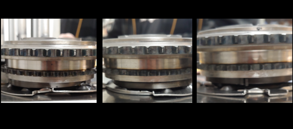
Fig. 14
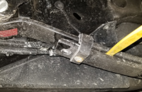
If excessive clearance of the actuator ring is suspected, the blades of the ring can be measured through the CMP sensor hole with a tire depth gauge after removing the water pump. (Fig. 15)
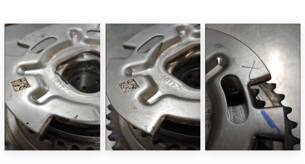
Fig. 15
All new actuators should be carefully inspected on a bench for flatness before installation to ensure a damaged part is not installed in an engine. TAC has seen some damaged actuators in reman engines.
There also have been some cases where the timing chain shoe breaks and rides up the chain, causing interference between the ring, tensioner and timing cover.
TIP: A number of engine actuators, including HFV6 engines and 4-cylinder engines, use this interrupter spacing, so these diagnostic tips may be helpful when repairing other vehicles.
– Thanks to Phil Forster, Tim Lightfoot, Don Langer and Bryan Salisbury


great information but its missing cam signal compared to the crank signal. need this information for all other engines.
great information, thanks!