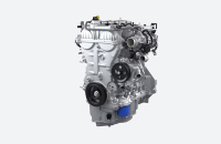
The belt driven electronic power steering system on the 2020-2026 Silverado 1500 and Sierra 1500 features a belt drive and ball nut mechanism, power pack, torque sensor and a rack and pinion steering gear. The power pack contains the power steering control module, sensors, and the power steering motor.
The power steering control module and motor apply power assist through the belt drive and ball nut mechanism to the steering rack to help reduce the amount of effort needed to steer the vehicle. The power steering control module can detect any malfunctions within the electric power steering system. Any malfunction that disables steering assist will cause the Service Power Steering message to be displayed on the Driver Information Center.
New Service Procedure
The power pack can now be replaced as a separate repair procedure, which offers a new way to address several issues with steering performance or possible noise concerns. Replacing only the power pack (motor and module) provides a more cost-effective repair than replacing the entire steering gear. New labor code operations have been released to support the new procedure.
Refer to Power Steering Assist Motor Replacement in the appropriate Service Information.
Power Pack Replacement
Replacing the power pack requires the use of the J-24319-B Steering Linkage and Tie Rod Puller to remove the right-side steering linkage outer tie rod from the right-side steering knuckle. In addition, the steering gear boot and right-side steering linkage inner tie rod must be removed.
The wiring harness and extension harness should be inspected for any damage. Do not repair the harnesses. If either harness is damaged, the harness must be replaced.
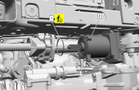
Next, remove the power steering assist motor access cover and the power steering assist motor, or power pack. (Fig. 1)
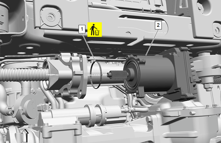
Fig. 1
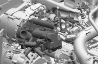
Also remove the electric belt drive rack and pinion steering gear belt and discard it. (Fig. 2)
Inspect the steering gear housing and power steering assist motor shaft for signs of water intrusion or corrosion. Replace the entire steering gear if there is any water or corrosion present.
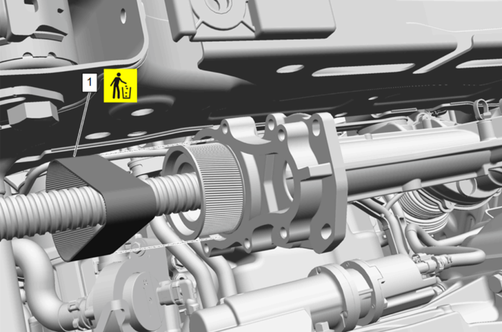
Fig. 2
When installing the power steering assist motor, make sure it is not at an angle or misaligned with the electric belt drive rack and pinion steering gear housing. The motor must be completely flush with the steering gear housing with no gaps present. The belt also must be completely installed on the pully. Any misalignment of the belt on the pulley will damage the belt and the steering gear will need to be replaced.
Setting Belt Tension
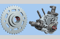
After installing the new belt on the power steering assist motor pulley, the GE-50576-A Acoustic Belt Tension Tester is used to achieve the proper belt tension. (Fig. 3)
TIP: If the GE-50576 tester is not available, the CH-51450 PicoScope and accessories PIOTA144 (microphone) and PIOTA145 (sensor cable) can be used to measure the belt tension.
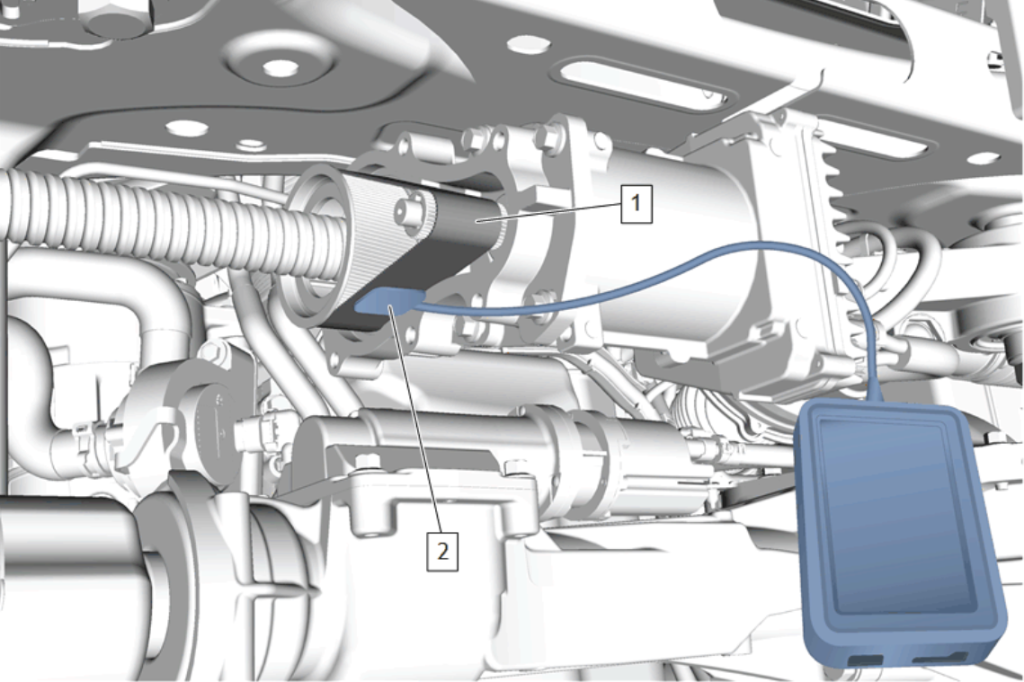
Fig. 3
Place the body of the tester on a flat surface or secure it to the electric belt drive rack and pinion steering gear housing. The tester cannot be held by hand while taking measurements. The readings will be inaccurate.
Position the microphone of the tester 6 mm (0.25 in) from the belt.
Use an allen wrench or finger to strum the belt three times to get an average belt tension reading. Strum the belt as close as possible to the center position between the two steering gear pulleys to achieve the most accurate readings. The average belt tension reading should be between 245 Hz – 265 Hz.
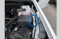
If the average reading is above or below the specification, loosen the power steering assist motor pivot bolt (Fig. 4) and rotate the motor clockwise to increase the tension or counterclockwise to reduce the tension. Increasing the belt tension increases the frequency. Reducing the belt tension reduces the frequency. Tighten the pivot bolt and test the belt tension again three times. Once the correct tension is achieved, tighten the four power steering assist motor bolts to specification.
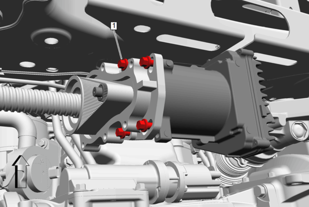
Fig. 4
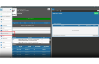
To program the new control module, select K43 Power Steering Control Module on the SPS Supported Controllers screen.
After completing programming and setup, measure and adjust the front toe as needed. Refer to the Wheel Alignment Specifications in the appropriate Service Information.
TIP: The labor time for the power steering assist motor replacement includes SPS programming. For front toe adjustment, use the applicable labor code to add time to the labor hours.
– Thanks to Brett Holsworth