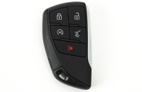
While the conventional horn system (Fig. 10) has been a common feature found on automobiles for decades, the pedestrian alert system is a relatively new system on hybrid and electric vehicles that provides several exterior audible alert functions. These two systems operate independently and use different component groups.
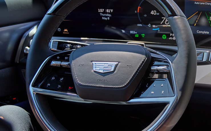
Fig. 10
Horns and Pedestrian Alerts is the ninth topic in the TechLink series highlighting several of the related systems handled by the Body Control Module (BCM) on GM models built with the Vehicle Intelligence Platform (VIP). The goal of this series is to help improve understanding of the components operated by the BCM and reduce warranty claims and unnecessary component replacement.
The earlier systems in the series are the Keyless Entry System, Content Theft Deterrent, Door Latch Actuators, Tire Pressure Monitoring Systems, Exterior and Interior Lighting, Fixed and Moveable Windows, Mirrors, and Wipers and Washers.
COMPONENT BREAKDOWN
- Body Control Module
- Pedestrian Alert Control Module (if equipped)
- Horn
- Steering wheel horn contact
- Steering wheel airbag coil
- Horn relay
- Horn fuse
- Pedestrian sound alert speaker – front (if equipped)
- Pedestrian sound alert speaker – rear (if equipped)
- Pedestrian Alert Control Module fuse (if equipped)
HORN SYSTEM OVERVIEW
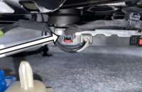
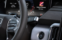
In the conventional horn system, the horn contact, located within the steering wheel assembly, links the circuit to a single- or dual-note electrically powered horn. (Fig. 11)
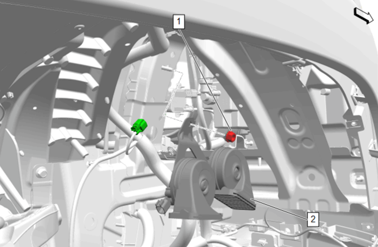
Fig. 11
In a typical configuration, the ground side of the horn(s) is constantly grounded, while the control side of the horn receives voltage usually from a relay located in a junction block. When the horn pad on the steering wheel is pressed, the control signal that has traveled from the BCM through the steering wheel airbag coil and then the steering wheel horn contact is pulled to ground. The grounded signal from the steering wheel horn contact tells the BCM that a horn sound request has been received. The BCM then outputs a command to the corresponding circuit relay to energize the horn output circuit, which sounds the horn.
The BCM may activate the vehicle’s horn system for the following reasons:
- Steering wheel horn contact switch has been pressed
- Theft deterrent system has detected a theft event
- Panic button has been depressed on the vehicle’s remote control door lock transmitter
- Keyless entry system has been used to lock the vehicle
- OnStar system (if available/equipped) has requested the BCM to enable the horn system
For more detailed system component locations, circuit layout, connector end views, and enablement criteria, refer to the vehicle’s diagnostic documents in the appropriate Service Information and the Owner’s Manual.
PEDESTRIAN ALERT SYSTEM OVERVIEW
In addition to the conventional single- or dual-note horn, select hybrid and electric vehicles are equipped with the pedestrian alert system, another form of an exterior-mounted warning system, due to the absence of audible engine noise. The system is sometimes referred to as the pedestrian friendly alert system (PFAS). At low operating speeds, typically under 18.6 mph (30 km/h), the Pedestrian Alert Control Module sends signals to the pedestrian sound alert speakers to alert surrounding individuals of the presence of an otherwise silent-moving vehicle.
The pedestrian alert system will be activated when the proper enable conditions are met, such as when the vehicle is in Propulsion Active or Run mode and the vehicle’s transmission or drive unit is in any forward gear, neutral, or reverse. The sound is programmed to change with vehicle speed and may continue beyond the 18.6 mph (30 km/h) threshold.
The pedestrian alert system is supplied battery voltage from a shared electrical system junction block and, in some cases, through a fuse shared with other vehicle systems. The Pedestrian Alert Control Module is externally grounded and is connected to the BCM via a LIN serial data circuit. The Pedestrian Alert Control Module supplies the pedestrian sound alert speaker(s) with both positive control and ground control. Refer to the vehicle’s electrical system wiring schematics in the appropriate Service Information for more detailed fuse and circuit information.
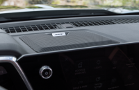
Not all vehicles equipped with the pedestrian alert system will use two pedestrian sound alert speakers. (Fig. 12) Some vehicles, such as the 2025 Corvette E-Ray and 2026 Corvette ZR1X, only utilize a front-mounted pedestrian sound alert speaker whereas the 2026 Silverado EV and 2026 Sierra EV use front- and rear-mounted pedestrian sound alert speakers. Refer to the vehicle’s appropriate diagnostic documents for more detailed information and speaker count.
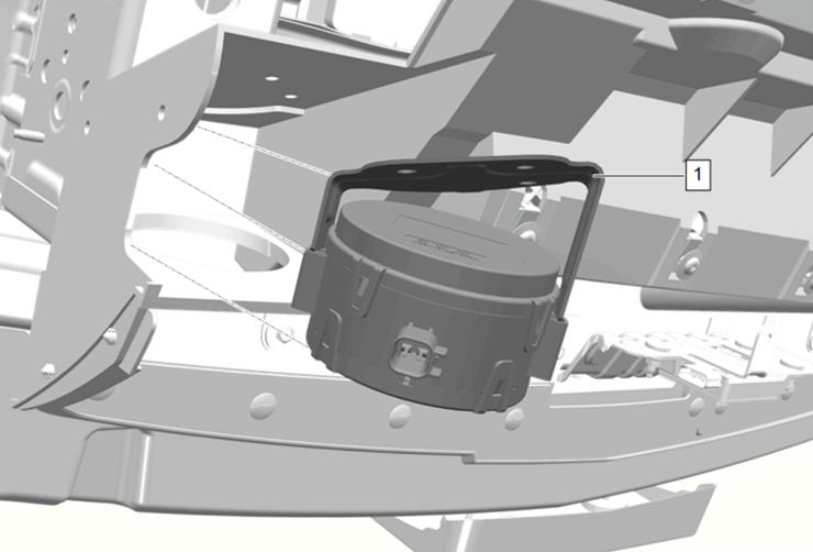
Fig. 12
HORN SYSTEM TOPOLOGY
The following graphic illustrates a representative communication structure for the horn system. (Fig. 13)
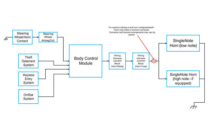
Fig. 13
PEDESTRIAN FRIENDLY ALERT SYSTEM TOPOLOGY
The structure of the pedestrian alert system is highlighted in the following graphic. (Fig. 14)
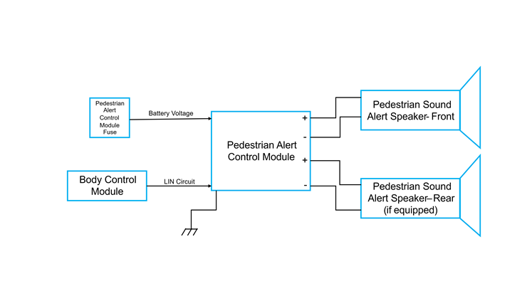
Fig. 14
DIAGNOSTIC STRATEGY
Before beginning any diagnostics, first verify the customer concern by duplicating it on the vehicle. Review the Strategy Based Diagnosis document before diagnosing any vehicle-related concern. Be sure to check for any applicable Preliminary Information documents or Technical Service Bulletins related to the horns or pedestrian alert system.
Prior to replacing a suspected faulty control module, verify the control module is equipped with the latest available software (if the module is programmable). Clear all DTCs and perform any necessary component learn or reset procedures according to applicable Service Information diagnostic documents.
To help pinpoint and correct the concern — and avoid unnecessary component replacement and warranty costs — make sure to have the proper GM-authorized tools before beginning any electrical circuit and system diagnostics, including a digital multimeter such as the Fluke 87, which is recommended for vehicle electrical circuit and system testing. It provides true RMS measurements and can capture peak MIN/MAX values. An authorized scan tool such as the EL-52100 Multiple Diagnostic Interface 2 (MDI 2) also is required.
When diagnosing a vehicle with a horn or pedestrian alert system fault, verify all associated system devices are communicating. Use the available scan tool data to check for any communication DTCs and investigate those before proceeding. If the concern is not accompanied by a DTC, perform a BCM power reset by disconnecting the vehicle’s negative 12 V battery cable for approximately one minute. Refer to the vehicle’s specific Service Information procedures for disconnecting and reconnecting the 12 V battery. For horn-related concerns, also monitor the horn switch status within the BCM using the scan tool.
For additional details, refer to Body Systems > Horns and Pedestrian Alerts in the appropriate Service Information.
– Thanks to Dylan Fantin