Power windows offer great convenience to drivers and passengers. The moveable windows often can be operated with a single touch of a switch. Although much more convenient than a manual window with a hand crank from the old days, power windows and their related systems also are more complex.
Fixed and Moveable Windows (Fig. 10) is the sixth topic in the TechLink series highlighting several of the related systems handled by the Body Control Module (BCM) on GM models built with the Vehicle Intelligence Platform (VIP). The goal of this series is to help improve understanding of the components operated by the BCM and reduce warranty claims and unnecessary component replacement.
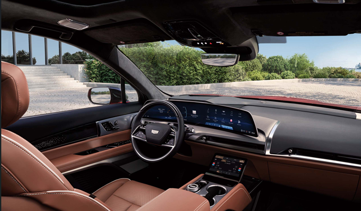
Fig. 10
The earlier systems in the series are the Keyless Entry System, Content Theft Deterrent, Door Latch Actuators, Tire Pressure Monitoring Systems, and Exterior and Interior Lighting.
COMPONENT BREAKDOWN
- Body Control Module
- Lighting Control Module
- Heater and Air Conditioning User Interface Control
- Front Side-Door Window Control Switch – Driver and Passenger
- Rear Side-Door Window Control Switch – Left and Right
- Front Side-Door Window Regulator Motor – Driver and Passenger
- Rear Side-Door Window Regulator Motor – Left and Right
- Rear Window Defogger Grid (if equipped)
- Heated Wiper De-Ice/Heated Windshield Grid (if equipped)
MOVEABLE WINDOWS SYSTEM OVERVIEW
Moveable windows allow occupants to open and close the glass. Fixed windows—such as the windshield, rear window, and fixed side or quarter glass—remain stationary.
Moveable-window systems include door-mounted side windows that use physical switches to open and close the windows. (Fig. 11) In some configurations, the window switches communicate with the BCM. The BCM evaluates the request, checks for conditions that may inhibit window movement, and communicates with the applicable window motor.
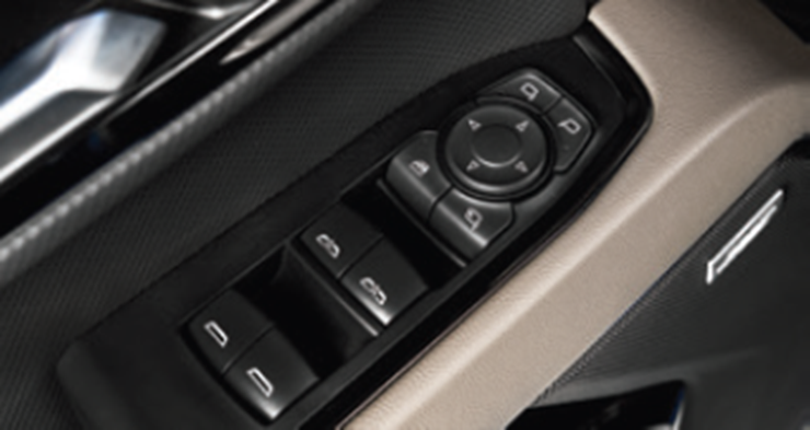
Fig. 11
In other configurations, the rear window switch up/down control circuits are directly connected to the rear window regulator motor, allowing the local switch to command window movement. A separate LIN communication circuit may still connect the rear window switch to the BCM. This LIN circuit allows the BCM to monitor switch status, coordinate commands from the driver/master switch, support the window-lockout feature, and communicate commands back to the rear window switch. For example, when the window lockout feature is enabled, the BCM can send a disable command to the rear window switches.
TIP: Exact circuit operation varies by vehicle configuration. Refer to the applicable schematic and Power Windows Description and Operation document for the vehicle being serviced.
Express Functions
For vehicles equipped with express-down windows or express-up-and-down windows, the driver and passenger doors contain smart window motors. These motors are designed to detect excessive resistance while performing the express-up function and will automatically reverse direction to help reduce the risk of a pinching injury to any occupants between the closing window and the door frame. Note that the automatic-reversal feature can be overridden by pulling and holding the appropriate window control switch.
Window Lockout
On vehicles equipped with power actuated rear side windows, independent control of the rear windows can be disabled. Refer to the Power Windows Description and Operation document in the appropriate Service Information for switch location, which can vary from vehicle to vehicle. This function is often referred to as the window lockout switch. When window lockout is enabled, the rear windows cannot be operated from their respective switches but can still be controlled from the driver side-door window control switch.
FIXED WINDOWS SYSTEM OVERVIEW
Fixed windows, or stationary glass panels, include the windshield, rear window, and fixed side or quarter windows. (Fig. 12) These windows do not open or close and are typically attached to the vehicle body with adhesive.
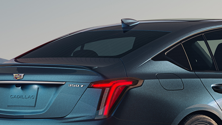
Fig. 12
Rear Window Defogger
Where equipped, the rear window defogger can be turned on with a physical switch or through a user-interface control, including the infotainment display on some vehicles. The switch or display sends a serial-data request to the BCM. The BCM then energizes the rear window defogger relay, which closes its contacts and allows battery-positive voltage to flow through the rear window defogger grid.
Glass Breakage Sensors
On select vehicles, the rear window defogger grid also serves as an input to the BCM for the theft-deterrent system through the glass-breakage sensors. (Fig. 13) When the theft-deterrent system is armed and the completed circuit through the rear window defogger experiences an open-circuit condition, such as due to a broken rear window, the BCM detects that an unwanted glass-breakage event has occurred.
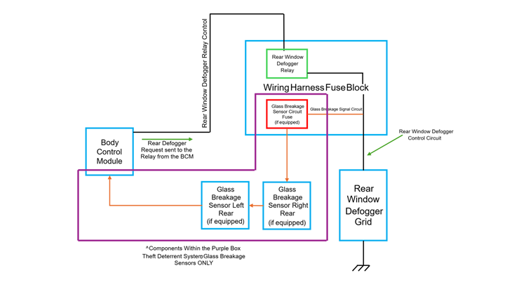
Fig. 13
Select vehicles also may have fixed side windows that are equipped with breakage sensors (Fig. 14), such as 2026 Escalade and Escalade ESV.
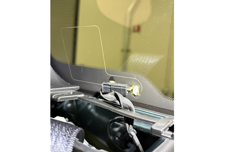
Fig. 14
Heated Windshield
Some models also feature an optional heated-windshield system, sometimes called a heated wiper de-ice system or windshield defogger. (Fig. 15) This system uses a different control path where the heating and air-conditioning (HVAC) user interface sends a serial-data request to the Lighting Control Module, which controls the applicable windshield-heater relay or system output.
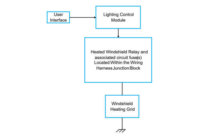
Fig. 15
The operating conditions for the rear window defogger and heated windshield or heated wiper de-ice system can vary by vehicle. Some configurations require the vehicle to be in propulsion-active or engine-running mode before the feature can be turned on. Refer to the vehicle owner’s manual, schematic, and Description and Operation document in Service Information for the exact operating conditions.
MOVEABLE WINDOW SYSTEM TOPOGRAPHY
The following graphic illustrates a representative communication structure for a moveable-window system. (F16) Exact network and circuit configurations vary by model.
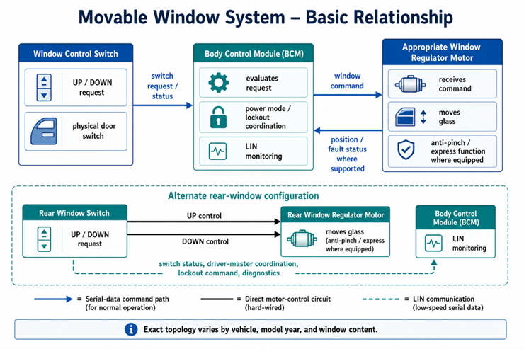
Fig. 16
The relationship between the driver window switch and the window regulator motor is highlighted in the following graphic. (F17) It provides an overview of the applicable power, ground, command, and communication paths.
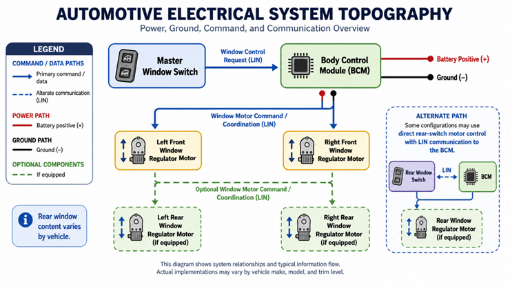
Fig. 17
SYSTEM DIAGNOSTIC STRATEGY
Before beginning down a diagnostic path, verify the customer concern by duplicating it on the vehicle. Review the Strategy Based Diagnosis document in Service Information, and check for applicable Preliminary Information documents or Technical Service Bulletins related to the fixed- or moveable-window system.
To help pinpoint and correct the concern—and avoid unnecessary component replacement and warranty costs—make sure to have the proper GM-authorized tools before beginning any electrical circuit and system diagnostics, including a digital multimeter such as the Fluke 87, which is recommended for vehicle electrical circuit and system testing. It provides true RMS measurements and can capture peak MIN/MAX values. An authorized scan tool such as the EL-52100 Multiple Diagnostic Interface 2 (MDI 2) also is required.
When diagnosing a vehicle with a fixed or moveable window system fault, verify that all associated window devices are communicating and use the available scan-tool data to monitor the window switch position data when physically toggling the window control switches. Scan the vehicle for any communication DTCs, and be sure to investigate any communication DTCs before proceeding. If the concern is not accompanied by a DTC, removing and reinstalling the BCM fuse(s) may correct the issue.
Before replacing a suspected faulty control module, verify that it has the latest available software, if applicable. Clear all DTCs and perform any required component learn or reset procedures as specified in the applicable Service Information diagnostic procedures.
For additional details, refer to Body Systems > Fixed and Moveable Windows in the appropriate Service Information.
— Thanks to Dylan Fantin