
The low tire pressure MIL may be illuminated along with a message on the Driver Information Center on some 2024-2026 Acadia, Traverse; and 2025-2026 Enclave models. In addition, the tire pressure learn procedure may not be able to be completed for one or both of the front tires. DTCs C1171 (Tire Pressure Monitoring Sensor = Left Front Internal Electronic Failure), C1172 (Tire Pressure Monitoring Sensor = Right Front Internal Electronic Failure), C1173 (Tire Pressure Monitoring Sensor = Left Rear Internal Electronic Failure), and/or C1174 (Tire Pressure Monitoring Sensor = Right Rear Internal Electronic Failure) also may be set.
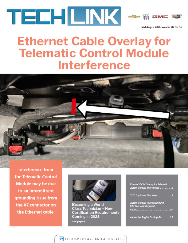
These conditions may be caused by interference from the Telematic Control Module (OnStar module) due to an intermittent grounding issue from the X7 connector on the Ethernet cable. To correct these conditions, replace the Ethernet cable with a cable overlay.
TIP: If only DTCs for the rear tire pressure monitors are setting, it is a separate issue not related to this condition.
Remote key fob-related issues also may be present when accompanied by one or more of the DTCs listed above. If intermittent key fob issues are present along with Tire Pressure Monitor (TPM) codes, it is possible the new overlay will resolve the fob concerns too.
TPM Relearn
If the TPM sensors for the front tires cannot be learned, lower the rear headliner trim panel. Do not remove the headliner trim panel. Disconnect the X7 connector from the Telematic Control Module and attempt to relearn the TPM sensors. (Fig. 7)
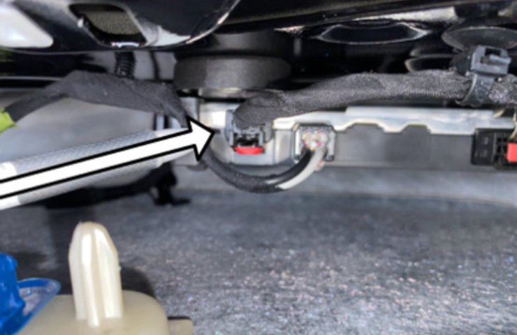
Fig. 7
If the TPM sensors are able to learn, continue with the Ethernet cable replacement. Otherwise, follow the appropriate Service Information procedures.
Access the Cable
To access the Ethernet cable, it will be necessary to remove or loosen several interior trim pieces, including the Rear Compartment Floor Stowage Compartment Divider, Right-Hand Front and Rear Side Door Sill Garnish Molding, the Center Pillar Lower Trim Panel, Right-Hand Quarter Upper and Lower Rear Trim Panel and Left-Hand Quarter Upper Trim Panel. (Fig. 8) Refer to the appropriate Service Information for each component.
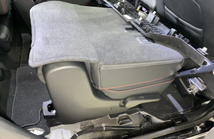
Fig. 8
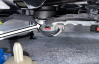
At the lower right side of the front passenger compartment, disconnect the X205 Ethernet cable connector. (Fig. 9)
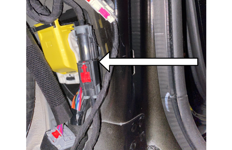
Fig. 9
Next, disconnect the X7 Ethernet cable connector from the Telematic Control Module in the headliner.
The existing Ethernet cable is bundled with the body wiring harness. The service Ethernet cable will be routed next to the body wiring harness. The terminals must be removed from the existing Ethernet cables to ensure they are not used in future repairs. Cut both ends off the existing Ethernet cable at X205 and X7 of the Telematic Control Module. (Fig. 10, X7 shown) Wrap PVC electrical tape around both ends of the cable. The unused cable can remain bundled with the body wiring harness.
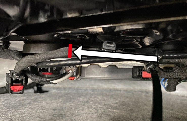
Fig. 10
Transfer Housings
Transfer both terminal housings to the new Ethernet cable. The new cable will come without housings.
On the X205 housing, remove the rear clip and save it for the new cable.
The release tab on each terminal housing is difficult to see with the cable installed. Follow the middle ridge to the back of the housing where it locks onto the cable. Lightly press the tab to release the cable. (Fig. 11)
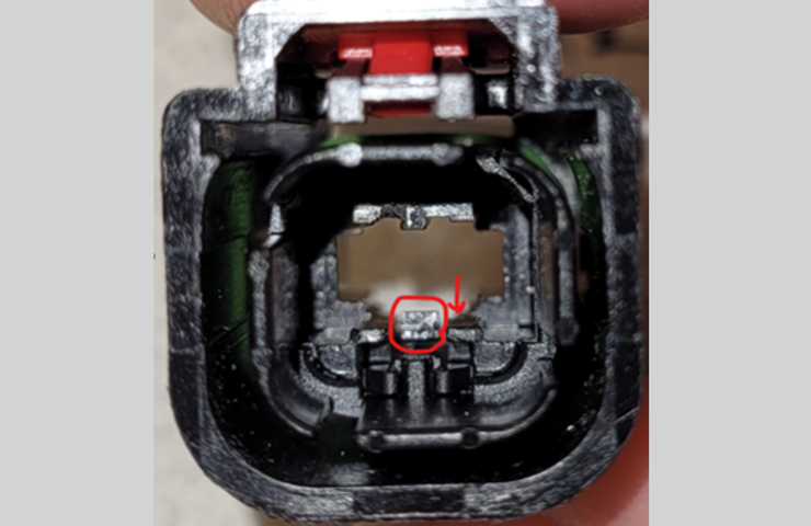
Fig. 11
Replacement Cable Routing
To route the new service Ethernet cable, start at X205 and follow the body wiring harness back toward the Telematic Control Module. Use extreme care when handling the new service Ethernet cable. Avoid kinks, sharp bends, pinch points and excessive wire tie tightness.
The replacement Ethernet cable routing is shown below in green. (Fig. 12)
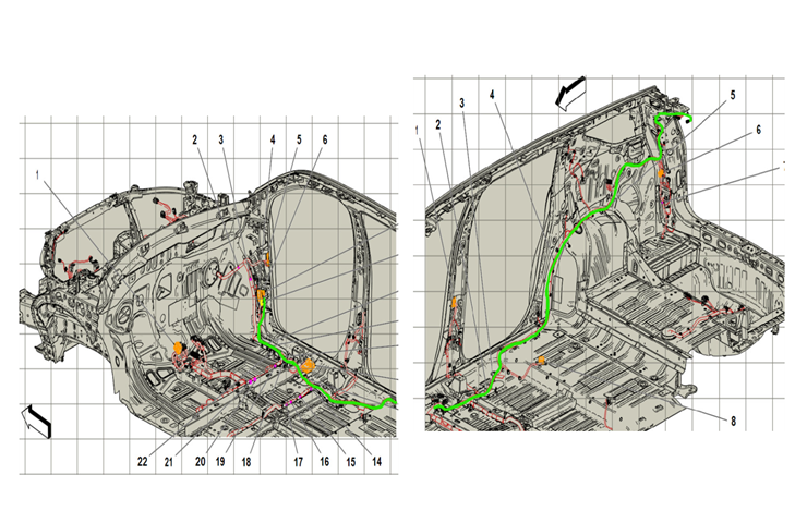 Fig. 12
While routing the new cable, be sure to leave plenty of slack so that the cable will not pull on the X7 connector at the Telematic Control Module. Make a small loop to remove some of the excess cable and secure with a wire tie near the Rear HVAC area. (Fig. 13) This extra cable can be used if there is not an adequate slack in the cable when connecting to the X7 connector.
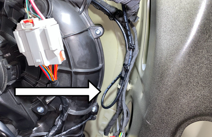
Fig. 13
Once the replacement cable is routed, connect to X7 of the Telematic Control Module. Secure the replacement cable to the body wiring harness with wire ties as needed to ensure the replacement cable does not move or rattle. (Fig. 14)
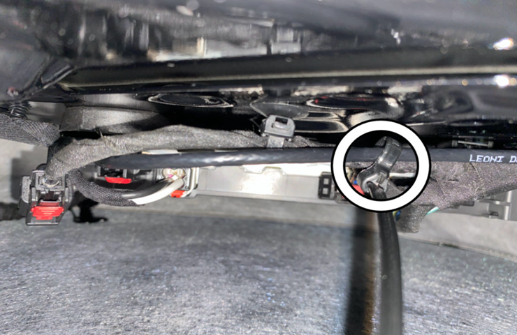 Fig. 14
For complete details on accessing the cable, transferring the housings, and routing the replacement cable, refer to Bulletin #24-NA-166.
– Thanks to Jessica Thoma













The PN in the bulletin is a specific part to address the Ethernet cable overlay procedure only for the listed models. The cable length is appropriate for the repair and the bulletin procedure outlines how to secure any slack. It is not a general procedure for Ethernet cable repairs. Refer to the appropriate SI procedure for more information when performing other wiring repairs.
would it be possible to have a list of all the lengths and part numbers available?
since it’s an overlay and the connector body is transferred, and thus not model specific,
the only variable is length between connections and/or modules.
thanks