The Body Control Module (BCM) on GM models built on the Vehicle Intelligence Platform (VIP) — first introduced in the 2020 model year — acts as the central controller for a wide range of body systems, including lighting, doors and windows, security, HVAC, and many others.
This article is the first in a new TechLink series that will highlight several of the related systems handled by the BCM. The goal of this series is to help improve understanding of the components operated by the BCM and reduce warranty claims and unnecessary component replacement. Each article will take a look at how a system works, its related components, and the best way to approach diagnosis when encountering a fault.
The first system in the series is the Keyless Entry System.
COMPONENT BREAKDOWN
- Keyless Entry Transmitter
- T10 Antennas
- Body Control Module
- Remote Function Actuator
- Tire Pressure Monitoring Sensors
SYSTEM OVERVIEW
Active Keyless Entry
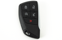
Active Keyless Entry refers to the method of keyless entry where a user presses a button on the Remote Keyless Entry transmitter (key fob). (Fig. 1) Any button press on the keyless entry transmitter may be referred to as an “active button press.” Upon an active button press, a signal is transmitted from the keyless entry transmitter to the K77 Remote Function Actuator. This signal is then filtered via the Remote Function Actuator and is sent via serial data to the K9 Body Control Module (BCM). If the ID from the keyless entry transmitter matches the ID to the transmitter learned, the action to the corresponding button press is executed by the BCM.
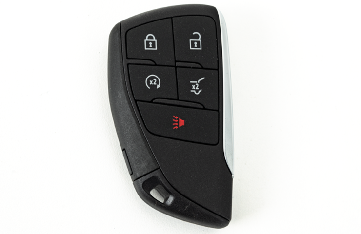
Fig. 1
Passive Keyless Entry
Passive Keyless Entry refers to the method of keyless entry where a user approaches the vehicle with a paired keyless entry transmitter and presses a button on a closure of the vehicle (such as a door handle, rear closure, or front closure). (Fig. 2) Upon pressing a button on a closure, a signal is sent to the BCM to activate a T10 Keyless Entry Antenna. Upon being activated, the keyless entry antenna will then transmit a signal to the keyless entry transmitter. The keyless entry transmitter will then transmit a signal back to the vehicle via the K77 Remote Function Actuator. The Remote Function Actuator will then send this signal back to the BCM and the requested function will be executed.

Fig. 2
Passive Starting
Passive Starting refers to the method of starting the vehicle with the keyless entry transmitter away from the backup pocket in the vehicle. When a user presses the S38 On/Off Vehicle Switch (or brake pedal in vehicles equipped with passive power moding), the BCM will activate the interior T10 Keyless Entry Antennas. These antennas will then send a signal to the keyless entry transmitter, which in turn will transmit a signal that is then interpreted by the K77 Remote Function Actuator. The Remote Function Actuator will then send a command via LIN to the BCM notifying a vehicle start has been requested and is allowed. The BCM then enables the appropriate start sequence.
KEYLESS ENTRY SYSTEM TOPOGRAPHY
Keyless Entry System components (Fig. 3) include:
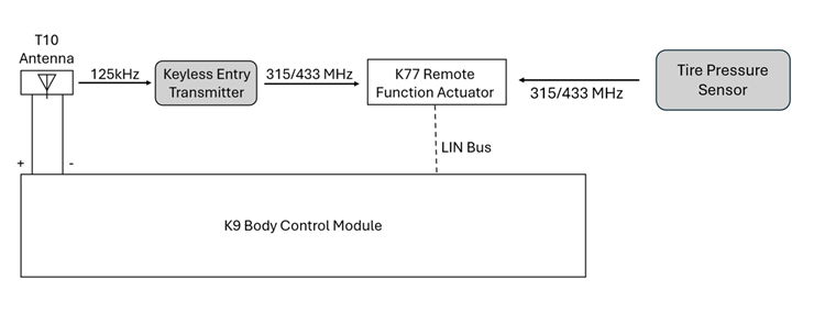
Fig. 3
SYSTEM DIAGNOSTIC STRATEGY
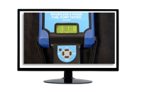
Prior to beginning any diagnosis of the Keyless Entry and Keyless Starting systems, it is important to have the required special tools on hand, such as the EL-52545 RF and TPMS Diagnostic Tool (Fig. 4), as well as an appropriate Digital Multimeter, such as a Fluke 87. The Fluke 87 is recommended for circuit/system testing as it is a true RMS meter capable of capturing peak MIN/MAX.
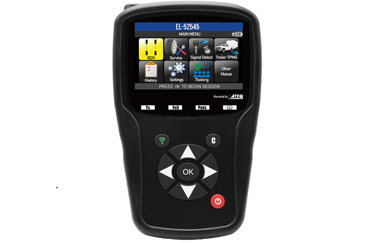
Fig. 4
In some cases, removing and reinstalling the BCM fuse(s) also may correct concerns that are not accompanied by a DTC.
Be sure to reference any applicable PIs or technical service bulletins related to the Keyless Entry System, including #PIC5650 (applies to all vehicles) and #PIT6456.
Keyless Entry System Malfunction
The Keyless Entry System Malfunction procedure is designed to diagnose any keyless entry concern that is not accompanied by a DTC. If a keyless entry concern sets a DTC, follow the appropriate diagnostic procedure in Service Information.
The Keyless Entry System Malfunction procedure begins by first outlining a series of tests designed to isolate the various features that make up the keyless entry system, such as active entry, passive entry, passive starting, etc. Each of these tests must be performed prior to any circuit/system testing. Once all tests have been completed, refer to the chart in SI (Fig. 5) below to determine what circuit/system testing must be performed based on the outcome of each test. This narrows down the overall diagnostic time by focusing on the feature that needs to be addressed.
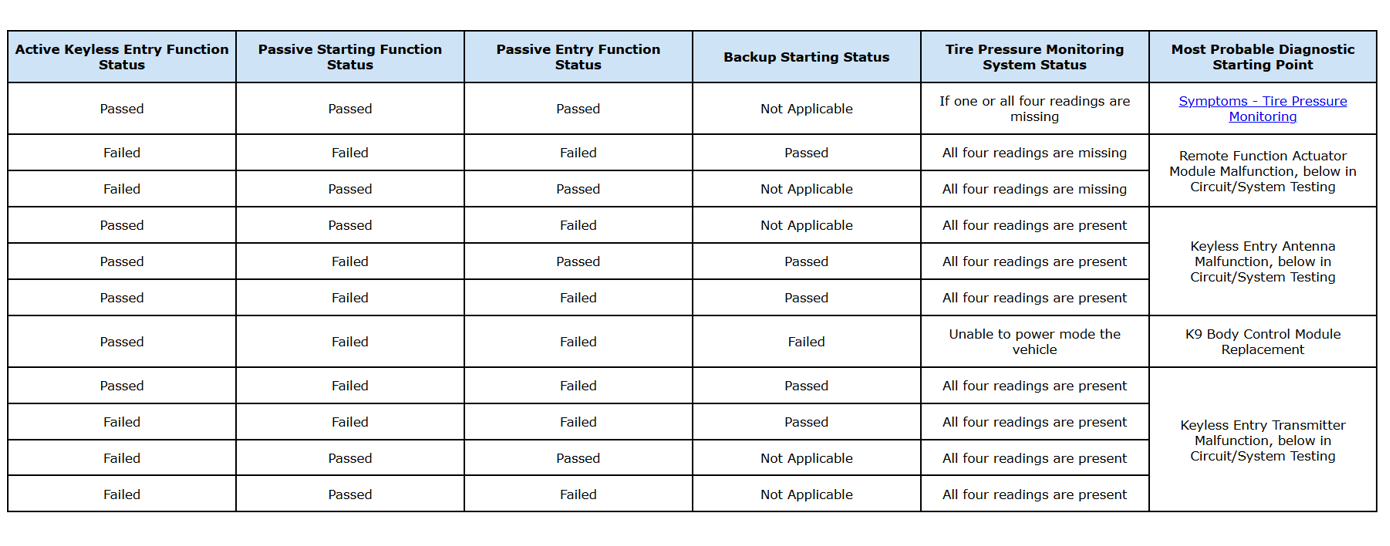
Fig. 5
TIP: Before replacing any components, verify transmitter operation, antenna response, DTC status, and applicable Service Information diagnostics.
For more information, refer to Safety and Security > Remote Functions in the appropriate Service Information.
– Thanks to Colin Day