
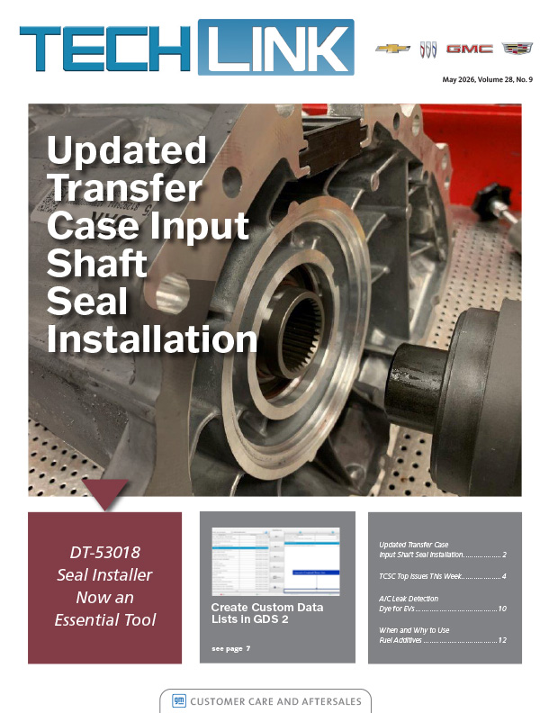
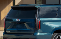
While driving in extremely cold weather conditions, poor engine performance may be noticed on some 2013-2021 Encore and Trax models equipped with the 1.4L engine (RPO LUV). (Fig. 10) The poor performance may be related to a crankcase vent tube plugged with ice, ice forming in the intake manifold and blocking the PCV passage in the cylinder head and ice accumulation in the charge air cooler.
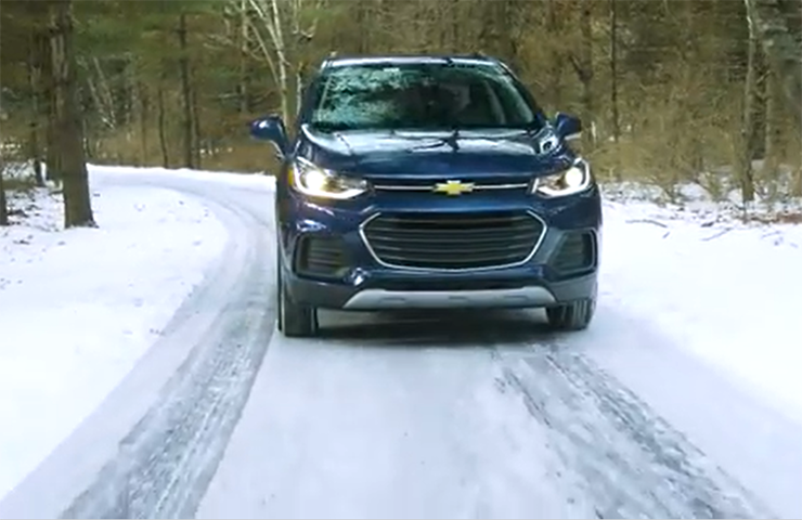 Fig. 10
As a result, there may be a loss of power, hesitation on acceleration, an oil leak or other performance issues along with DTCs P0299 (Engine Underboost), P0234 (Engine Overboost), P2227 (Barometric Pressure (BARO) Sensor Performance) and P00C7 (Intake Air Pressure Measurement System – Multiple Sensors Not Plausible).
If any of the conditions are determined to be caused by freezing or icing, inspect the following components: grille winter cover, heated PCV bypass system, modified Charge Air Cooler (CAC), and CAC outlet air elbow duct. If not previously installed, install the grille cover, heated PCV bypass, modified CAC and elbow duct.
If these components have been installed and icing has been verified in extreme cold, perform the Intake Air Pressure and Temperature Sensor Inspection and Cleaning procedure and the CAC drain procedure. Check Bulletin #16-NA-405 for details.
If contamination (ice, water, oil or sludge) is found at the charge air bypass valve, refer to Bulletin #22-NA-067 for intake manifold replacement. It is not recommended to clean or flush the intake manifold or bypass solenoid.
Grille Winter Cover
A grille cover should be installed when operating the vehicle in extremely cold weather conditions. (Fig. 11) The cover may appear to be undersized and may stretch during installation to ensure a tight fit. Warm the vinyl cover to ensure that it will be pliable and easier to install onto the front bumper fascia.
The cover attaches to the fascia using hooks pushed through the grille opening. Make sure all hooks are engaged for a secure fit.
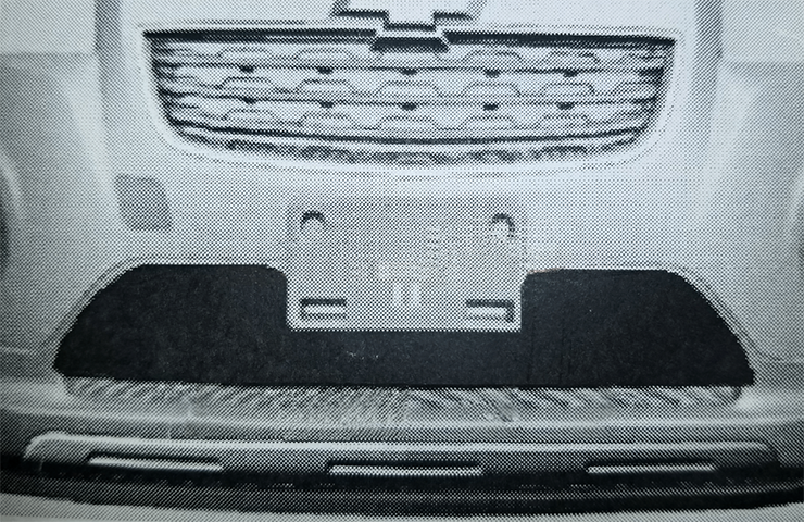 Fig. 11
Charge Air Cooler Outlet Air Elbow Duct
Inspect the charge air cooler through the inlet to determine if the vehicle has the new or old design. If the charge air cooler is the old design (Fig. 12, shown with an X below), replace the charge air cooler. If the charge air cooler is the new design (Fig. 12, shown with a check mark below), which has wider fin spacing and a division in the middle of the charge air cooler, replacement is not necessary.
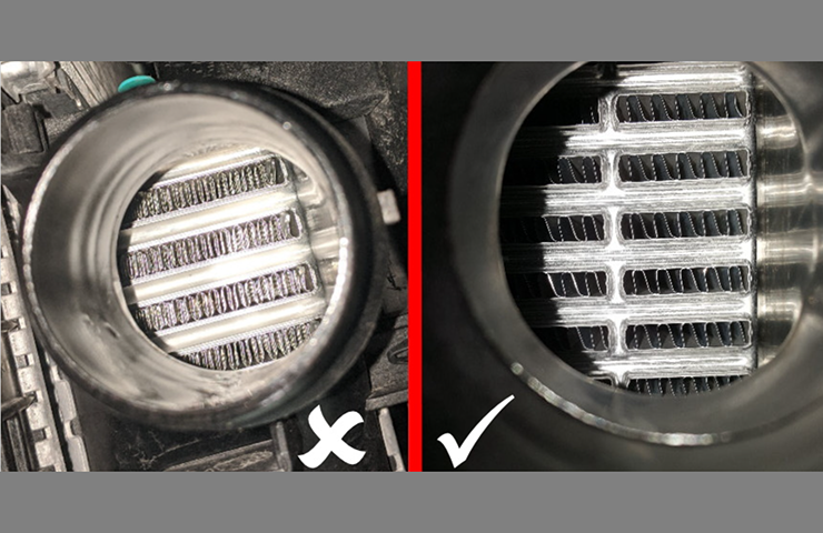 Fig. 12
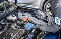
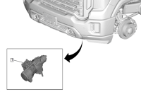
When installing the new elbow duct (Fig. 13), first remove and clean the Intake Air Pressure and Temperature (IAPT) sensor. Remove the bands that secure the air hoses to the elbow duct and install the new elbow duct onto the air hoses, aligning the duct to the marks. The new elbow will have an estimated 45-degree mounting surface for the IAPT.
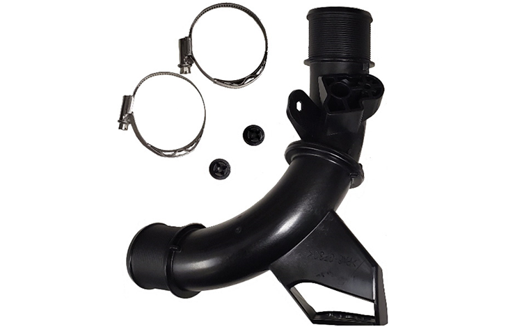 Fig. 13
PCV Heater
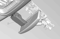
The PCV heater also should be installed into the air cleaner outlet duct and air resonator assembly. (Fig. 14) It may have been previously installed on the vehicle.
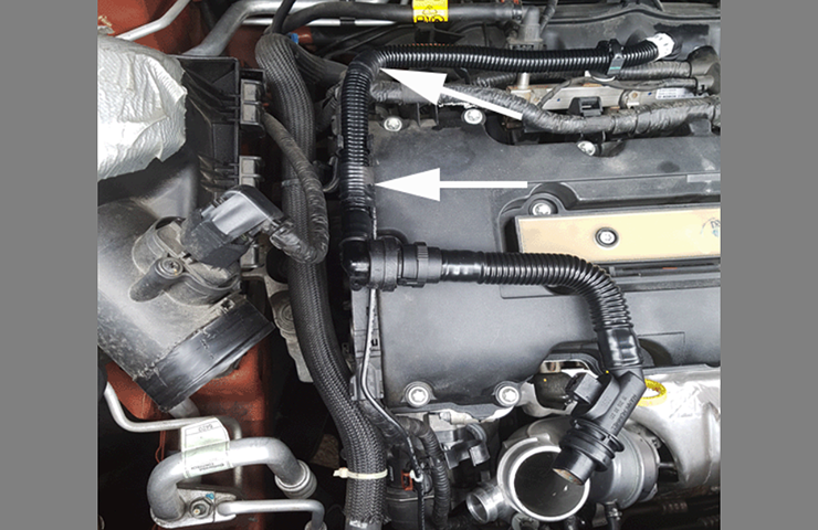 Fig. 14
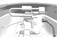
The PCV heater wiring harness terminal is connected to different cavities in the fuse block depending on the model year. (Fig. 15) Refer to Bulletin #16-NA-405 for information on connections for 2013-2016 models and 2017-2020 models. Route the PCV heater wiring harness across the engine wiring harness.
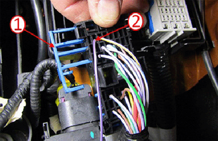 Fig. 15
Charge Air Cooler
If the revised charge air cooler has been installed, drain and reinstall the CAC. (Fig. 16)
If the CAC has not been replaced, install the new modified CAC.
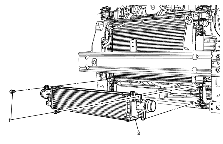 Fig. 16
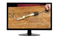
Intake Air Pressure and Temperature Sensor Inspection and Cleaning
If all the components have been installed, remove the Intake Air Pressure and Temperature (IAPT) sensor and inspect for any contaminates. (Fig. 17)
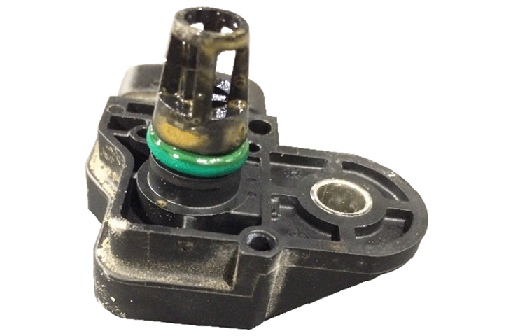 Fig. 17
Do not use any chemical cleaners or water, or use compressed air, to clean the sensitive IAPT sensor. Allow time for any ice build-up to melt by placing the sensor port down.
Refer to Bulletin #16-NA-405 for additional information and part numbers.
– Thanks to Scott Willems


