
A hesitation or misfire sensation may be felt in some upfitted 2023-2025 Express and Savana vehicles when passing below high-voltage power lines. The following DTCs may be set in the Electronic Brake Control Module (EBCM): C0045-0F, C0050-0F, C0800-5A, C0800-03, U0100-00, U0125-00, U0140-00 and U0401-00. DTC U0073-00 also may be set in the Engine Control Module (ECM).
Illuminated MILs displayed on the instrument cluster can range from a Traction Control light flicker to multiple brake system warning lights with part of the Driver Information Center display going blank.
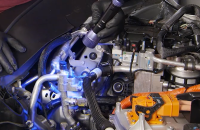
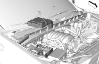
These conditions may be caused by the aluminum roof bows of an upfitter box, which may be acting as an antenna when passing under the high-voltage lines. (Fig. 6) The roof bows will dissipate electrical spikes into the vehicle’s electrical system. The proximity of the EBCM to the ungrounded portion of the vehicle may be why most of the DTCs are related to the EBCM.
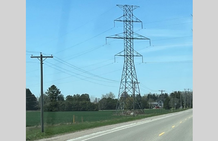 Fig. 6
GDS2 Freeze Frame Data may show that the rear wheel speed sensors appear to have momentarily increased in speed. PicoScope voltage measurement across battery terminals will intermittently spike in voltage to over 30V at times. (Fig. 7, A. Prior to adding ground cable; B. After ground cable installation)
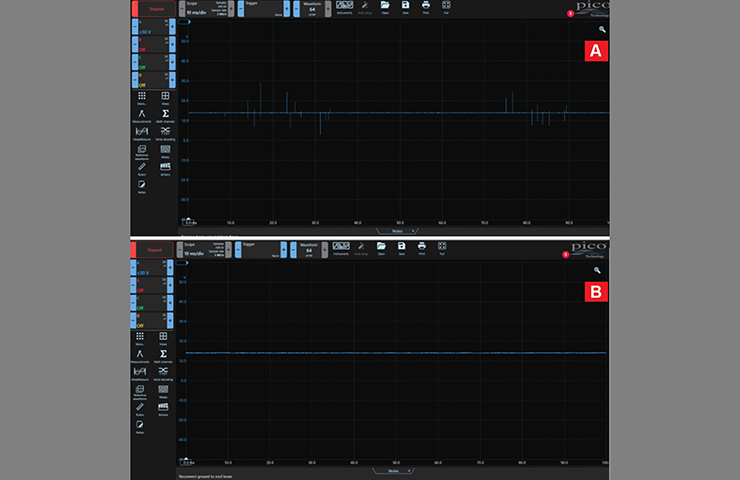 Fig. 7
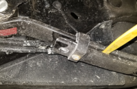
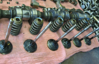
The movement in a fiberglass box may have the roof bows touching the lower grounded angle bracket at times, which explains why the conditions can be very intermittent. In order to alleviate interference into the electrical system, at least the first three roof bows of the upfitter box need to be grounded.
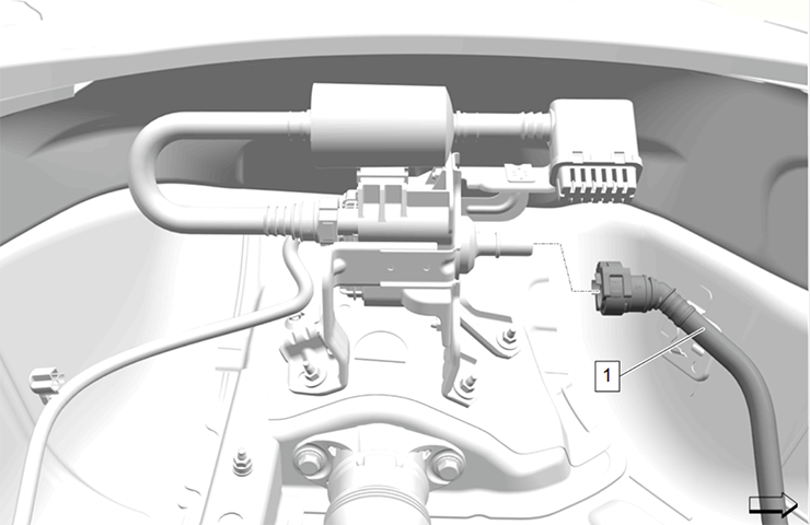
Ground cable and cable ground eyelets can be purchased through most local auto parts stores. The ground cable installation across the first three roof bows requires 7 feet of #4-gauge ground cable, which should be attached to the bottom of the first three roof bows and then grounded to the vehicle frame. (Fig. 8)
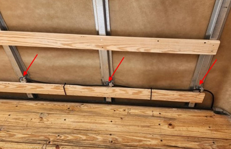 Fig. 8
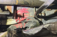
TIP: The roof bows must use a flexible ground cable when installing directly to the floor angle brace. (Fig. 9) Using the incorrect length or type will limit movement of the fiberglass box sides and lead to stress cracks in the fiberglass box.
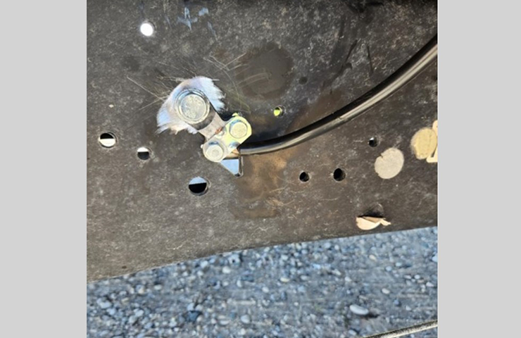 Fig .9
Prepare the aluminum surface before installing the grounding. It is recommended to use rivet nut inserts in the bows.
Spray or coat the ground bolt/ring terminal on the frame with an anti-corrosion sealant in order to prevent rusting.
For more information, including additional installation tips, refer to Bulletin #25-NA-274.
– Thanks to Rich Renshaw


