
In the simplest terms, electricity consists of the movement of electrons, which flow through batteries, wires, switches, and other conductors. A common comparison is that electrons in a wire flow like water in a hose. The flow of electrons is called electrical current and the pressure that causes current to flow is called voltage.
For example, pinching a garden hose while the water is flowing creates a resistance to water flow, and the pressure inside the hose would be lower after the water passed the resistance. Electricity is similar. Any time current in a circuit flows through a resistance, the voltage is lower after it’s passed through the resistance. The proper name for this is voltage drop, and there’s a relationship between the size of the resistance, the amount of current flow, and the amount of voltage drop. This is expressed by the mathematical formula called Ohms Law: Current = Voltage / Resistance.
To find voltage: Voltage = Current x Resistance
To find resistance: Resistance = Voltage / Current
If there are several resistances arranged one after the other in series, the voltage drops further each time it passes through each resistance. Ultimately, the voltage in a circuit will drop from source voltage to zero volts as the current moves from and returns to the source.
Measuring Voltage
Measuring voltage is actually measuring the difference between electrical pressures at two different places in an electrical circuit.
The battery negative terminal and anything in the vehicle that is connected directly to it are collectively referred to as “ground.” If both leads from the EL-39200 Digital Multimeter (DMM) are touched to the same point in a circuit — even at the battery positive terminal — the DMM reads zero, because there’s no difference between them.
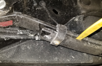
It’s customary to measure voltage in a vehicle with reference to the battery negative terminal or ground. If the negative DMM lead is touched to the battery negative terminal and the positive lead is touched to another part of the electrical system, the DMM will indicate how many volts difference there is between the two points. (Fig. 13)
 Fig. 13
With reference to the battery negative terminal (ground), the place the voltage is highest is at the source — the battery positive terminal. This is called B+, battery voltage, or source voltage.
TIP: Since electronic components may be sensitive to test voltages, do not perform any tests on circuits unless directed to do so in the appropriate Service Information.
Voltage Drop
Voltage drops must be measured in a live, functioning circuit, with current flowing. If there is an open, the voltage drop reading is meaningless.
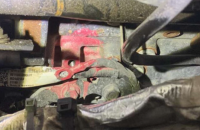
To measure voltage drop directly between two points in a circuit, set the DMM to the V (DC) position and select the MIN MAX function. Place the positive DMM lead ahead of the suspected resistance and the negative lead after the resistance. With the circuit operating, the meter readout showing the difference in voltage between the two points is the actual voltage drop. (Fig. 14)
 Fig. 14
TIP: A DMM has polarity. If the readout indicates a negative number, reverse the leads.
Whenever voltage is dropped by an unwanted resistance, there’s less voltage left over to power the intended load in the circuit. For instance, a corroded terminal in a starter motor cable connector (an unwanted resistance) uses up some of the voltage that should be available for the starter motor. The result (an unwanted voltage drop) causes poor or no cranking. If any voltage drop is higher than acceptable, be sure to disconnect the appropropriate terminals and look for corrosion and damaged wiring or any other conditions that may cause an open/high resistance in the circuit.
Every circuit contains built-in voltage drops. For instance, each load is a voltage drop. The voltage is dropped when a motor runs, a relay clicks, or a lamp is illuminated. And nearly every sensor in a computer-controlled engine management system works on the voltage drop principle. A sensor that drops too little voltage can cause as much of a problem as one that drops too much.
Another kind of voltage drop occurs in all circuits. These voltage drops are not intentionally designed in, but they’re unavoidable and have to be accounted for. Every component in a circuit — every length of wire, every switch, every terminal — offers some resistance to current flow. Each of these resistances cause a tiny, but measurable, voltage drop. Engineers decide how much voltage drop is considered normal and acceptable. Many diagnostic procedures provide specifications for acceptable voltage drops.
Resistance
Resistance is the opposition offered by a substance to the passage of steady electric current or, more specifically, the current flow within a circuit.
There are not any materials that offer absolutely no resistance, nor is there a material that has total resistance; but some materials come close to those extremes. Metals have relatively little resistance. Nonconductors — made from insulating materials such as glass, ceramic, rubber and plastic — have nearly infinite resistance.
Resistance is measured with the ohmmeter function of the DMM. The ohm is the standard measure of resistance.
Disconnect the power feed (i.e. fuse, control module) from the suspect circuit and disconnect the load. The presence of external voltage can upset the meter reading. The DMM measures resistance by sending a small current through the circuit.
The DMM leads can add 0.1 to 0.2 ohms of resistance to a measurement. Touch the leads together to read the resistance of the leads. To eliminate this built-in resistance, press the Relative (REL) mode (or Delta) button and the DMM will automatically subtract this value from the subsequent readings.
Place one lead to one end of the circuit to be tested and the other lead on the other end of the circuit to check the resistance. If a circuit shows low resistance, that means it has good continuity.
Resistance specifications are listed in many of the diagnostic procedures in the Service Information.
Be sure to follow all the diagnostic instructions in the appropriate Service Information, including the circuit /system testing procedures, before replacing any components.
– Thanks to Scott Barone


