
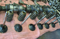
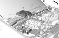
Some 2017-2019 XT5 and 2017 LaCrosse models may have a Service Transmission message displayed on the Driver Information Center along with one or more of the following DTCs: P0722, P0729, P0730, P0731, P0732, P0733, P0734, P0735, P073D, P073E, P07A2, P07E4, P07E5, and P1769. These conditions may be caused by misalignment of the coupler between the Transmission Range Control Module (TRCM) and the transmission. The TRCM (Fig. 14) will need to be re-centered.
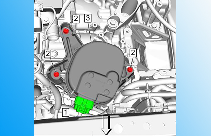 Fig. 14
The TRCM includes:
- Coupler to coupler, or lever to rod linkage interface with the transmission manual shaft.
- Backup Park Lock function (Default to Park)
Before re-centering the module, check the transmission fluid level. If the fluid is dark and has an overheated odor, any internal wear issues with the automatic transmission should be addressed.
Next, with the transmission in Park and the parking brake applied, perform the Backup Park Lock Actuator Disarming procedure.
The Backup Park Lock function is an electrically isolated smart actuator inside the TRCM that is activated when the transmission does not achieve Park. When the Backup Park Lock function is activated, the gear is disarmed, which rotates the torsional spring forcing the transmission manual shaft to the Park position. Disarm the Backup Park Lock Actuator using a scan tool when the rod linkage is adjusted (if equipped) or if the TRCM is being removed then reinstalled.
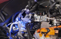
On XT5 models (Fig. 15), detach the Engine Control Module (ECM) from the brake assembly and move the ECM aside. It’s not necessary to disconnect the electrical connectors. Remove the ECM from the bracket.
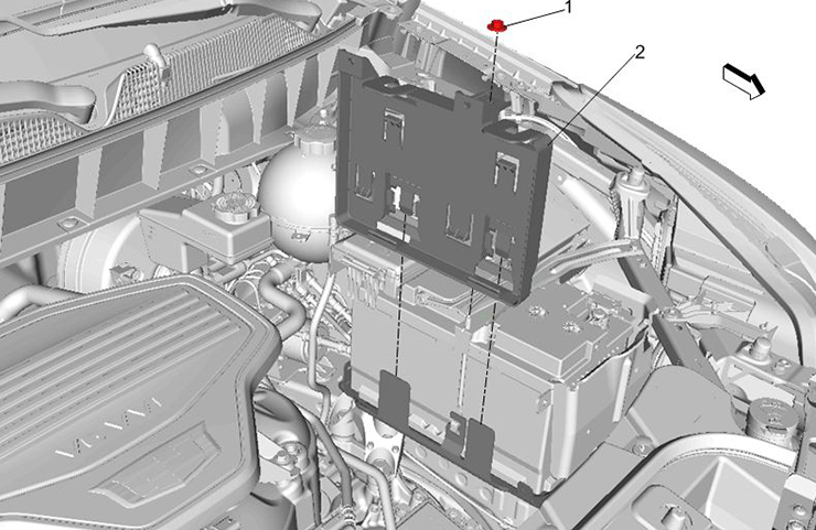 Fig. 15
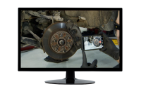
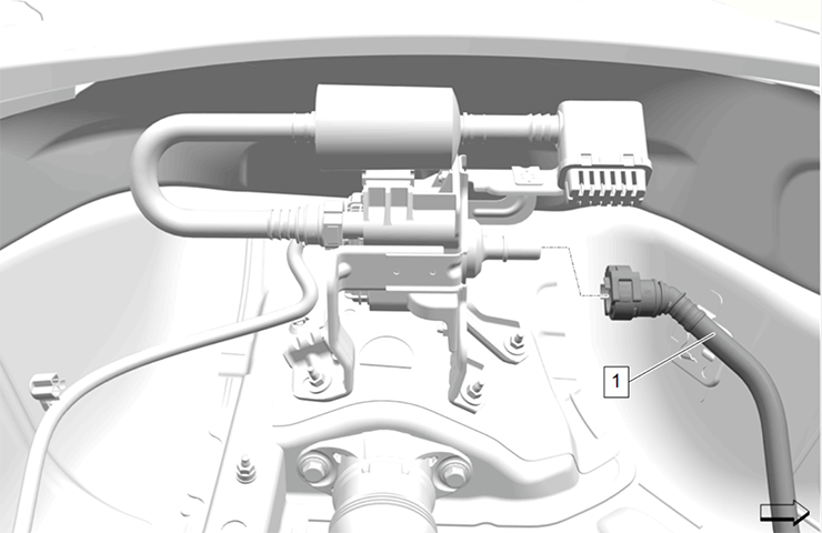
On LaCrosse models (Fig. 16), remove the air cleaner housing assembly. Also remove the bolt that secures the intake air duct to the core support and then remove the air cleaner bracket.
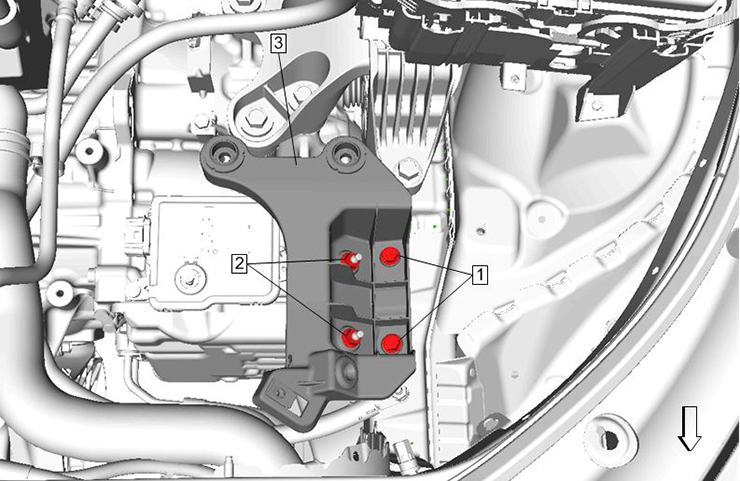 Fig. 16
With access to the TRCM, loosen (approximately 1/4 inch) the automatic transmission range selector actuator hardware module bolts.
Rotate the automatic transmission range selector actuator hardware module clockwise to the right lock position (Fig. 17, Blue line). Next, rotate the module counterclockwise to the left lock positon (Fig. 17, Green line). Finally, rotate the module clockwise until it is centered between both full lock positions (Fig. 17, Red line).
TIP: The turning radius of the module will be very slight when centering.
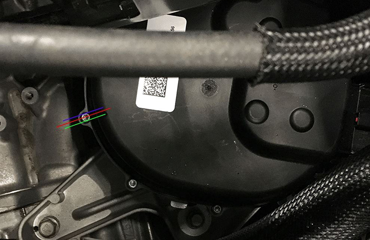 Fig. 17
Hold the module in place and tighten the hardware module bolts to prevent the actuator from moving from the center position. Tighten the bolts to specification.
With the module re-centered, perform the TRCM learn procedure (not for new modules). If the test fails, re-adjust the module and retest. The test fails again, refer to the appropriate Service Information for further diagnostics on the DTC set.
Refer to Bulletin #18-NA-083 for additional information.
– Thanks to Tom Burlingame


