
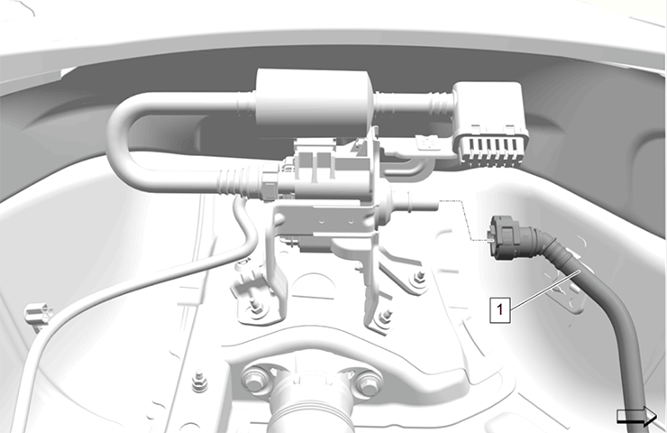
Components most likely to cause a parasitic draw on the 12V battery on GM models include switches, relays, LIN buses and control modules. A new voltage drop test in Service Information (SI) can help in determining which component may be causing a parasitic draw.
If there is an excessive load on the electrical system that is draining the battery after the ignition is turned off, review the Battery Electrical Drain/Parasitic Load Test document under 12V Charging and Starting > Diagnostic Information and Procedures in the Service Information. It features updated information on diagnostic aids, system verification and testing, including a new parasitic draw voltage drop test and a battery draw verification sheet to help with diagnosis.
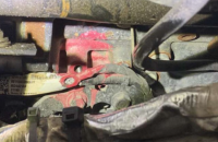
Several tables have been added in SI that list the milliAmps (mA) value across the fuses in a fuse block. Use a DMM set to mV scale to check the voltage drop between the battery positive post and each leg of the battery junction block (if equipped) to determine which fuse block contains the draw. (Fig. 1)
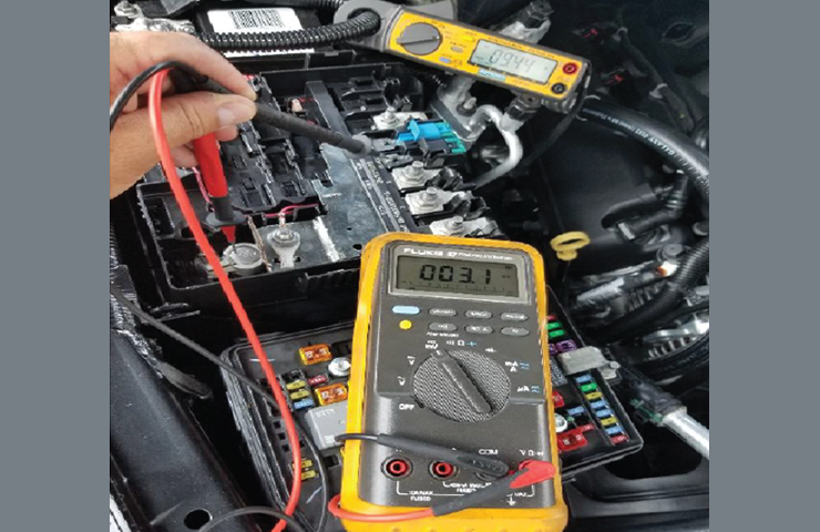 Fig. 1
Once the fuse block feed with the highest draw has been identified, go to that fuse block and check voltage drop across fuses, excluding J-case type fuses, one at a time. (Fig. 2) For three-bladed fuses, the center of the fuse is the supply voltage for both sides of the fuse. Compare the reading to the corresponding fuse in the table. If voltage drop is found, refer to the Power Distribution Schematics to diagnose exactly which circuit of a suspected system is causing the high parasitic drain.
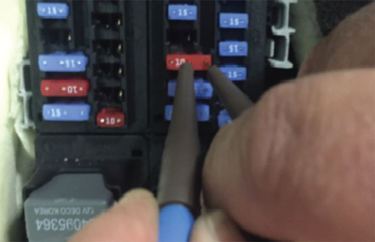 Fig. 2
Testing Set Up
To begin diagnosis of a parasitic draw, it’s important to properly set up the test. There are many things that can prevent the vehicle from completely going to sleep and passing the parasitic draw test.
- Road test the vehicle and operate all accessories to check for proper operation.
- Connect a 50 Amp inductive amp clamp to the negative battery cable that can read down to 1 mA.
- With the ignition Off, open all doors, hood, trunk/liftgate (to gain access to all components and fuse blocks) and manually close all latches and switches.
- Lock the vehicle with the key fob and move the fob a safe distance so it doesn’t wake up the vehicle (distance depends on approach detection of the vehicle).
- With all modules and components asleep, monitor the amperage. After approximately 10 minutes, amperage should drop to a stable value less than 20 mA.
- If amperage is 40mA or higher, follow the fuse voltage drop test to identify the fuse(s) with an ongoing draw.
- Measure all fuses and record voltage drop, fuse location, type and rating.
- After all fuses are tested, identify the suspect circuits and calculate the amperage for each.
If there are multiple control modules drawing amperage, work from the least complex component to the most. For example, for a drain on the Memory Seat Module, Body Control Module and Gateway Module, remove power to the Memory Seat Module first and verify if the other modules go to sleep properly. In many cases, a “satellite” module like the Memory Seat Module is the most likely to cause a system to wake up.
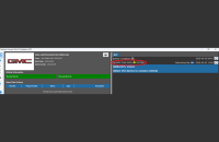
Battery Draw Customer Verification Worksheet
The new Customer Concern Verification Sheet (CCVS) Battery Draw worksheet may be helpful in isolating or duplicating a customer’s concern. Use the information during the road test to verify operation according to the customer’s description of the condition.
A link to the worksheet is included in the Battery Electrical Drain/Parasitic Load Test document in SI. The worksheet also can be found in GM GlobalConnect. From the Service apps, launch Service Forms and select CCVS Battery Draw. (Fig. 3)
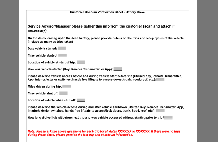 Fig. 3
All Customer Concern Verification Sheets (CCVS) have been designed to improve communications between service customers and technicians. The more clearly concerns and related symptoms are understood, the more likely the concern will be fixed quickly and accurately.
System Operation
When diagnosing a parasitic draw, keep in mind the power-down and wake-up process for most control modules.
After the ignition is turned off, the control modules will begin to go to sleep (shut off). However, not all control modules go to sleep at the same time. Some control modules may take up to 30 minutes or longer after turning the ignition off before going to sleep (e.g. Retained Accessory Power). Other components, such as EVAP, HVAC Afterblow, EV Battery Heater/Coolers, OnStar and Remote Keyless Entry (approach detection in keyless access vehicles), may periodically wake up control modules and then go back to sleep, depending on vehicle status. These are all normal conditions.
Most vehicle systems will go into the initial sleep cycle after 10 minutes. With periodic normal wake up cycles that will occur for approximately one second, it can take up to two hours before all systems power down completely. Typically, a vehicle will not have more than a 50 mA parasitic draw during the initial power sleep cycle.
There are many things that can prevent the vehicle from completely going to sleep and passing the parasitic draw test, such as the key fob not moved away from the vehicle (for keyless access vehicles); the approach, exit, or delayed lighting not disabled; or HVAC Afterblow, which is enabled at the factory on some 2021 models, cannot be disabled. Some vehicles can have the power supply port changed to “ON” with the key off to allow for accessories to stay powered (e.g., phone charger). Ensure all aftermarket accessories are unplugged prior to testing. The use of a Digital Multimeter (DMM) set to Min/Max may help identify the normal spikes in the parasitic draws.
– Thanks to Ernest Haller


Thank you for providing your feedback.
The document is to aid in locating a draw. Before going into the testing, we are looking for a draw over 40 mA. Once an excessive draw has been determined, we then begin the testing of the drop across the fuses rather than having the tech pulling fuses and risking it will reset an intermittent draw.
In the SI document, we inform technicians that there are several components that stay awake or periodically wakes up, which is normal, to help reduce misdiagnosis.
Based on your feedback, we did add additional notes in the SI document as follows: “Some fuses that always have a nominal draw going to components that supply memory retention is normal.”
We also recommend to use the parasitic draw reference tables along with the schematics to determine the excessive draw.
To view a video of the testing procedure, check out the January Emerging Issues seminar. Log in to the Center of Learning (via GM GlobalConnect) and then search for the 2021 SKH Seminar January Emerging Issues 10221.01V.
What are you looking at say a HVAC control module may stay on for an hour after key off so it will show a voltage drop of “X” a radio that keeps “time” will show a drop of “X” your just looking at current flow across each fuse with 50+ modules on these vehicles there could be 15 fuses that are Awake with the key off. the Buick encore has a bank of fuses that stay awake for days then the BCM shuts them off all of those fuses are going to show a voltage drop what normal and what’s not? I can see this process chasing your tail as well I really like the idea but a module can actually have a draw of .005Ma and it will show voltage drop across the fuse in the grand scheme of things that fuse is misrule for a draw. you could have a rear drive module that will not turn off have a darw of 125Ma and that will show a voltage drop across the fuse as well
Make a video
Be sure to check out the upcoming January Emerging Issues seminar, which will be available on January 14th on the Center of Learning.
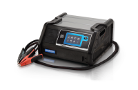
The tool shown in the photo is the Midtronics PDF 40 clamp meter.
J35590, For those asking what tool #.
what brand amp clamp is that tool
IS THERE AN INDUCTIVE CLAMP THAT GM RECOMMENDS? SEEMS MOST AREN’T ACCURATE DOWN TO LOW MILLIAMPS WE DEAL WITH.
I JUST checked a brand new 2021 1500 Silverado on a pdi and on terminal 4 of the battery underhood block I had .5 to 14.0 mv .. under this new test that is a draw and my amp meter was showing .14 ma on negative battery cable . I just got done spending 4 hours on a 2020 that had the same mv on terminal 4 .. just trying to figure out how to use this new test and to make sure its accurate because obviously the fluctuating mv on terminal 4 is normal ….
could you produce a video on this ..
I show .29 ma draw on negative battery cable ,battery tests good with gm battery charger. I have 5 to 14 mv on terminal 4 of battery junction box and 3 mv on blue terminal . o mv on 123 terminals and black terminal also . the chart shows I have a big draw by the amount of mv but my amp meter is showing 28 milliamps ?it does not make sense to me