
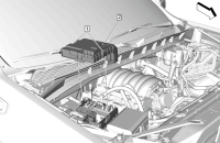
The 2022 Bolt EV and 2022 Bolt EUV are powered by a 65-kWh nickel lithium-ion high-voltage battery. The battery pack will be serviceable and some of the battery pack’s accessory components have been fitted under the front hood for easier access and maximum space efficiency.
The drive motor battery (Fig. 10) contains:
- 5 Battery Cell Sections (Rows)
- Battery Contactor Assembly
- High Voltage Bus Bars
- Manual Service Disconnect
- Battery Energy Control Module
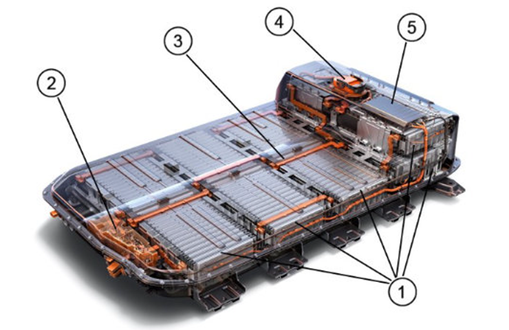 Fig. 10
The 288 individual lithium-ion battery cells of the drive motor battery are rated at approximately 3.65 volts each. A protective polymer-coated aluminum cover encases each cell to help prevent gas permeation and improve battery cooling efficiency. The system’s nominal voltage is 350 volts.
An integrated, liquid-cooling tray circulating 1.82 gallons (6.9 liters) of DEXCOOL™ coolant handles the cooling of the high-voltage battery. The battery pack also has a separate heating element for warm-ups in colder climates, as well as an automatic shut-off relay integrated into its wiring for emergencies.
TIP: The high-voltage battery pack will be on TAC Restriction and Exchange during the vehicle launch period. However, the individual section are not on exchange. Only trained technicians with the proper knowledge, tools and Personal Protective Equipment (PPE) should inspect, text and/or replace the high-voltage battery.
Battery Cells
An individual cell is configured horizontally with the negative tab on one end and the positive tab on the other. Each cell measures approximately 338 x 100 millimeters (mm), or 13.3 in x 3.9 inches (in), and weighs nearly 0.5 kilograms (kg) or 1 pound (lb.). Each battery cell contains a carbon anode (negative electrode), a nickel-rich lithium-ion chemistry cathode (positive electrode), and a safety-reinforced separator. The safety-reinforced separator provides the medium to transfer electrically charged ions between the anode and the cathode inside the battery cell.
Battery Cell Groups
Three cells are welded together in parallel to form 96 cell groups. These cell groups are clamped together in series to form 10 cell modules. Battery modules 5 and 7 have eight cell groups while the others contain 10. Two modules are physically assembled together to form a section, or row.
The modules are numbered 1 to 5 starting with the right forward-most module. Module 6 is in the rearward-most position on the left side, working forward to module 10. The cell groups increment in series, starting at the negative-most group 1 in module 1 and ending at cell group 96 in module 10. This is the typical numbering logic GM has adopted for most of their high voltage batteries, starting at the negative-most post and numbering the module to follow.
Battery Cell Sections
There are five battery cell sections, or rows. The sections are numbered starting at the front with section 1 and ending with the upper-most section at the rear as number 5. (Fig. 11) The sections physically contain two modules each, but the modules are not electrically connected. Modules 5 and 6, however, are electrically connected through the manual service disconnect.
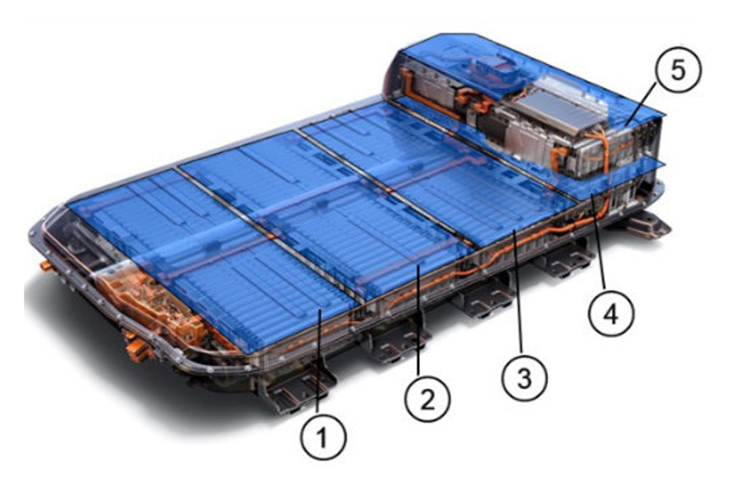 Fig. 11
Flexible, high current, copper positive and negative bus bars connect each battery section together in series. Manual service disconnect removal physically interrupts the series circuit within the battery assembly. During high-voltage battery service, be sure to identify the correct location for each bus bar prior to disassembly. It is possible to install some of the bus bars improperly, which can result in a short circuit.
TIP: The separated battery sections are live after system disabling. When servicing the internal battery components, high voltage is exposed. Always take the proper precautions and wear PPE when working in or around the high-voltage battery.
Drive Motor Control Module
The non-serviceable, flash programmable Drive Motor Control Module, contained within the Drive Motor/Generator Power Inverter Module, is controlled by the Hybrid/EV Powertrain Control Module 1. The Drive Motor Control Module controls the speed, direction, and output torque of the drive motor. The scan tool can communicate directly with the Drive Motor Control Module in order to retrieve data parameters only. Associated DTCs are set in the Hybrid/EV Powertrain Control Module 1.
Hybrid/EV Powertrain Control Module 1
The Hybrid/EV Powertrain Control Module 1, located in the Power Inverter Module, is the main controller of the powertrain. The Hybrid/EV Powertrain Control Module 1 determines when to perform normal operating modes and regenerative braking. Power modes can be displayed on the infotainment screen by selecting the leaf icon. (Fig. 12)
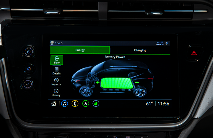 Fig. 12
The Hybrid/EV Powertrain Control Module 1 also operates in conjunction with the Hybrid/EV Powertrain Control Module 2 to determine when to enable and disable the DC high-voltage circuits. The Hybrid/EV Powertrain Control Module 1 sends commands to the Drive Motor Control Module to operate the applicable motor.
Hybrid/EV Powertrain Control Module 2
The Hybrid/EV Control Module 2, located inside the cabin, performs a number of functions, including processing information sent from the Battery Energy Control Module to learn the battery capacity, battery state of charge, and thousands of parameters as the high-voltage battery pack is discharged and charged.
Battery Energy Control Module
The Battery Energy Control Module (BECM) is internal to the high-voltage battery. The BECM collects temperature information from six sensors mounted to specific battery modules, as well as voltage from each cell group, through volt sense wires and total system current. Replacing the BECM requires a specific sequence to disconnect and reconnect in order to prevent internal damage due to voltage spikes.
Drive Motor Battery Charger
The on-board drive motor battery charger is located above the transmission and provides the mounting for the Accessory Power Module. The charger can create a maximum output of 11 kW during level 2 charging at 48 amps when running on a 60-amp circuit. The vehicle can achieve a full charge in about 7 hours with a hard-wired 48-amp charger vs. 10 hours using the 32-amp level 2 portable dual-mode charge cord. The level 1 portable cord set can take significantly longer and is intended only for situations where it is not possible to access a level 2 charge cord. Charging options can be selected on the infotainment screen. (Fig. 13)
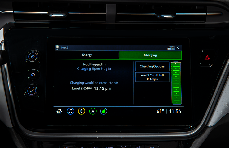 Fig. 13
When using the portable dual-mode charge cord:
- For level 1 charging, it is recommended to use a dedicated 20-amp outlet and ensure the charge rate limit is set to the 12-amp rate using the energy display. Location-based charging must be activated in order to achieve 12 amp charging.
- For level 2 charging, it is recommended to use a dedicated 50 amp outlet. At this level, the range yield will be about 25 miles (40 kilometers) per hour of charging.
For level 2 charging using a hard-wired 240V charge station with a dedicated outlet sized appropriately for the charger, set at 48 amps, the range yield will be about 37 miles (60 kilometers) per hour of charging.
For additional information, refer to Bulletin #21-NA-141.
– Thanks to Jonathan Johnson and Matt Bunting


