
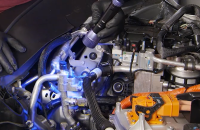
Proper timing chain installation on the High Feature V6 engine (RPO LGX, LGZ, LGY, LGW) requires confirming the location of the green-colored chain links. In order to get a proper perspective of the chain on the crankshaft sprocket, it’s critical to view the chain directly in front of the crankshaft.
Stage 2 Timing
If the green-colored links are not lined up before chain removal, correct timing still can be verified.
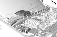
There should be 30 chain links, including the links on the timing marks, between the intake camshaft actuator timing mark (Fig. 4, #12) and the crankshaft sprocket timing mark (Fig. 4, #7).
There also should be 13 chain links, including the links on the timing marks, between the exhaust actuator timing mark (Fig. 4, #10) and the intake actuator timing mark (Fig. 4, #13).
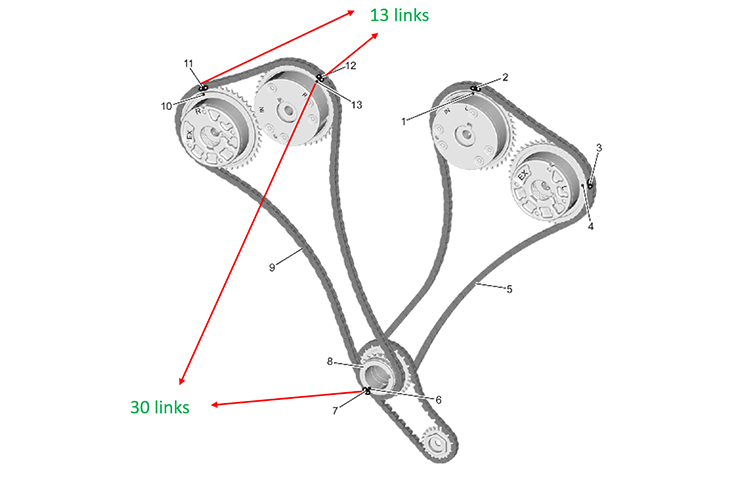 Fig. 4
To verify correct Stage 2 timing:
- Put the crankshaft keyway at the Stage 2 (3 o’clock) position.
- Count the links between the intake actuator timing mark and the crankshaft timing mark. It should be 30 links.
- Count the links between the intake actuator timing mark and the exhaust actuator timing mark. It should be 13 links.
TIP: Stage 1 and 2 chains are the same part number. Stage 1 and 2 crankshaft chain drive sprockets also are the same part number.
Stage 1 Timing
The correct Stage 1 timing also can be verified if the green-colored links are not lined up before chain removal.
Between the exhaust camshaft actuator timing mark (Fig. 5, #4) and the crankshaft sprocket timing mark (Fig. 5, #7), there should be 30 chain links, including the links on the timing marks.
Between the intake actuator timing mark (Fig. 5, #2) and the exhaust actuator timing mark (Fig. 5, #3), there should be 13 chain links, including the links on the timing marks.
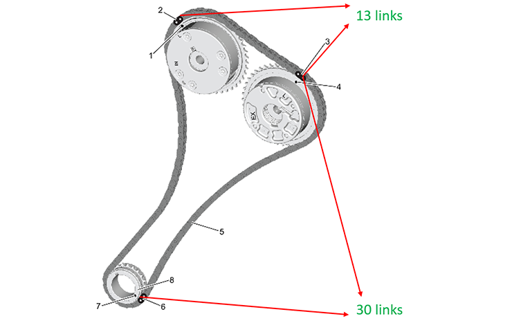 Fig. 5
To verify correct Stage 1 timing:
- Remove the Stage 2 chain and crank sprocket.
- Remove the oil pump chain and crank sprocket.
- Put the crankshaft keyway at the Stage 1 (11 o’clock) position.
- Count the links between the exhaust actuator timing mark and the crankshaft timing mark. It should be 30 links.
- Count the links between the intake actuator timing mark and the exhaust actuator timing mark. It should be 13 links.
Setting the Timing Chain
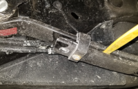
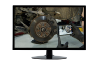
A common error when setting the chain timing is not looking straight on at the crankshaft sprocket, especially Stage 1.
From a high angle (Fig. 6), it is very difficult to see if the chain link is properly set on the crank sprocket timing mark.
 Fig. 6
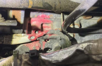
Even with the green-colored links not lined up prior to Stage 1 chain removal, counting the links can show that link number 30 is off one tooth from the timing mark. (Fig. 7)
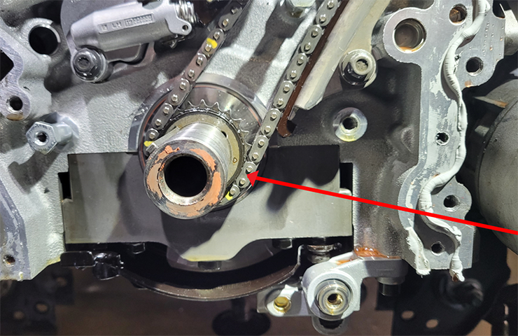 Fig. 7
From a higher angle, the chain may look correct, but with a straight-on view, it is easy to see it is off. Improper timing as shown may set Stage 2 DTCs P0018, P0019 and P0021.
When viewing the crankshaft straight on, it’s easy to see if the green-colored link is in the correct position to the sprocket timing mark. (Fig. 8)
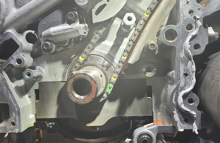 Fig. 8
Viewing the crankshaft at the correct angle — either visually or by using a camera — is critical to properly installation of the chain on the crankshaft drive sprocket.
– Thanks to Hank Poelman


