
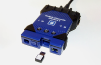
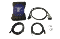
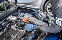
The EL-52552 COAX FAKRA Cable Adapter Kit can help in diagnosing a variety of coax cables, including Wi-Fi, cameras, headliner cables, A-pillar cables and more. Diagnosing coax cables routed through the headliner, for example, is made easier with the kit.
The COAX FAKRA Cable Adapter Kit covers all known cable configurations equipped with FAKRA (Fachkreis Automobil, a German standard) connectors. The adapters included in the kit are designed with universal FAKRA connectors, Z Code, in order to connect to all color-coded FAKRA connectors on the coax cables in the vehicle. (Fig. 1)
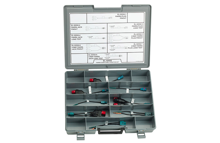 Fig. 1
If the Video Processing Module, radio or camera is not functioning properly, there may be a camera, coaxial cable or connector issue due to vibrations that are higher than the components can withstand. As a result, the coaxial cable connectors may have excessive resistance that interrupts the video signal, resulting in the black or blue screen in the vehicle.
Coax Cable Testing
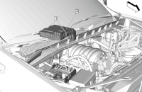
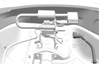
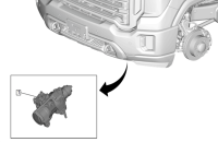
- The first step is to disconnect the inoperable camera at the module. The K157 Video Processing Module can be found in vehicles equipped with Surround Vision Camera System (RPO UV2, UVS) or Trailer Camera System (RPO UVI). Vehicles with the A11 Radio will be equipped with the Rear Vision Camera System (RPO UVB).
- With the ignition On, measure the voltage at the module. (Fig. 2)
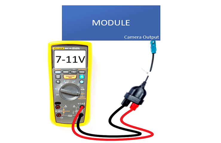 Fig. 2
- If voltage is not between 7 and 11 V, the module should be replaced.
- If the voltage is between 7 and 11V, disconnect the camera that is inoperable.
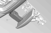
- Find the appropriate pinout adapter and load test loop adapter from the EL-52552 COAX FAKRA Cable Adaptor Kit.
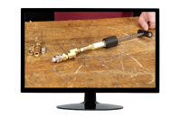
- Connect the two adapters together and measure the resistance between the terminals at the pinout adapter. (Fig. 3) Record the resistance for later use.
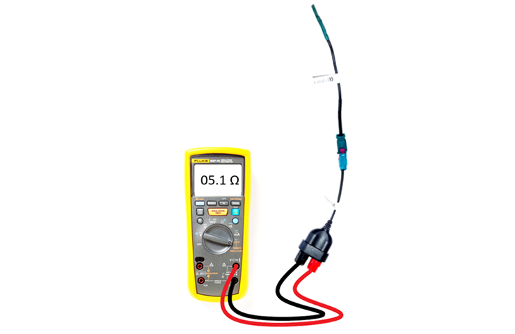 Fig. 3
- Disconnect the two adapters and connect each one to the appropriate end of the coax cable. (Fig. 4)
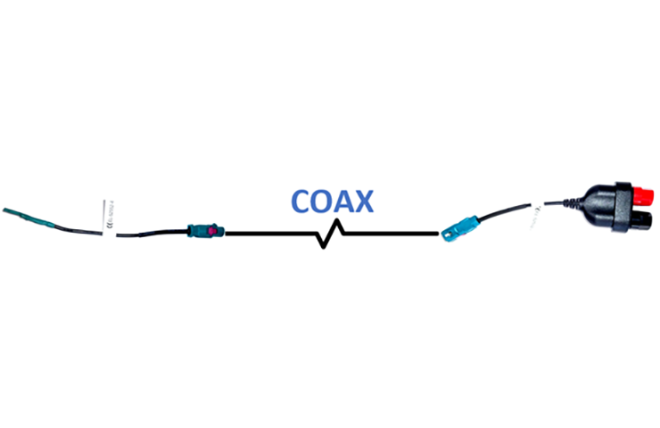 Fig. 4
- At the pinout adapter test terminals, measure the total resistance of the coax cable loop, including the connected load test adapter. (Fig. 5) If the resistance is not within 5 Ω of the reading taken in Step 6, replace the coax cable. If the resistance is within 5 Ω of the reading taken in Step 6, replace the camera.
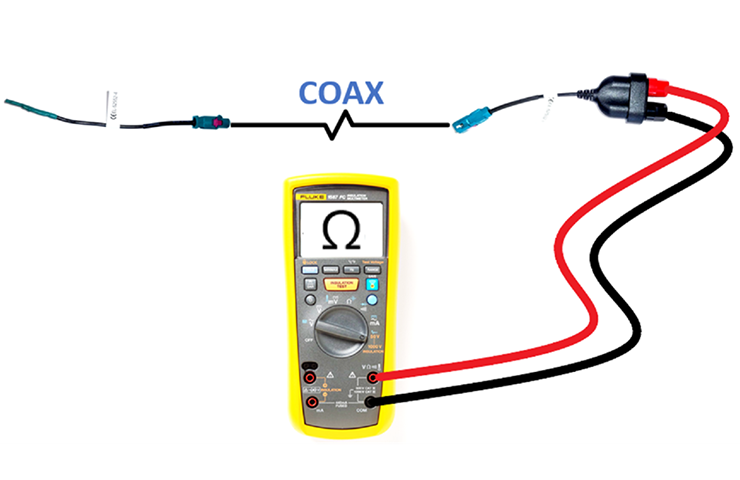 Fig. 5
- Reconnect all connectors and check if any DTCs are set.
- If a DTC is set, the module may need to be replaced.
Replacing Coax Cables
If it’s determined that the coax cable is the issue, the GM cable repair strategy is to replace these cables instead of repairing them when addressing related vehicle conditions. Never attempt to repair coax cables on a vehicle. The entire cable/harness or component must be replaced.
When replacing a faulty or damaged cable, first disconnect the cable connectors at both ends. Route the new cable along the harness and use tie-straps to attach the cable to the existing harnesses or brackets. Be sure to not pinch the cable or bend it more than a 2-inch (5 cm) radius. Tape or foam can be used to prevent the cables from rattling if needed.
With the new cable installed, reconnect the connectors to the components. Cut the connectors off the older cable as close to the harness breakout as possible without damaging the harness.
For more information about wiring repairs, refer to the appropriate Service Information. Be sure to always review the service procedures before beginning a repair to confirm the correct procedures are being followed.
– Thanks to Marco Salcedo


