
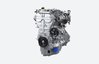
The Sliding Cam Valve Lift System (SCS) on the new 2.0L 4-cylinder, turbocharged engine (RPO LSY) in the 2019 XT4 delivers a combination of performance and efficiency with three distinct operating modes. The SCS system enables the Engine Control Module (ECM) to change the camshaft lift profile of the intake and exhaust camshafts while the engine is running. The SCS has four intake camshaft profile actuators and two exhaust camshaft profile actuators that vary the camshaft lift profile sleeve position axially on the camshaft in response to commands from the ECM.
SCS Profiles
The SCS system has three unique-sized cam lobes on each camshaft profile slider:
- Power Profile: High Lift — Full capacity, conventional lift and duration. In this profile, all four cylinders are active and all valves open to their maximum lift for when the full capability of the engine is needed. (Fig. 1)
 Fig. 1
- Economizer Profile: Low Lift — Reduced capacity (3 mm lift) changes the duration of the valve opening and closes the valve early. In this profile, all four cylinders are still active, but all intake valves open to a lower lift height to help save fuel under medium load conditions, such as highway driving. (Fig. 2)
 Fig. 2
- Ultimate Fuel Economy Profile: AFM — Cylinder deactivation, used for increased fuel economy in light load conditions, such as highway cruising. In Active Fuel Management (AFM) mode, cylinders 2 and 3 are deactivated. (Fig. 3)
 Fig. 3
When AFM is active, the system first turns off the fuel injectors of cylinders 2 and 3, followed by the exhaust valves and then the intake valves, which traps a cylinder’s worth of air with no fuel in the cylinder. The trapped air becomes an air spring to help the piston return in what would be the expansion stroke. Cylinders 1 and 4 are still active with their intake valves now opening to a lower lift height. The intake cam profile for the firing cylinders is the same low lift that is used in the Economizer profile. The engine produces the same power from the two active cylinders, but is operating at half of the Economizer profile power.
Sliding Cam System Components
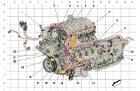
The components of the SCS include (Fig. 4):
- B339 Exhaust Camshaft Profile Sleeve Position Sensors (Qty 2)
- M130 Exhaust Camshaft Profile Actuators (Qty 2)
- M129 Intake Camshaft Profile Actuators (Qty 4)
- B23 Exhaust & Intake Camshaft Position Sensors (Qty 2)
- B338 Intake Camshaft Profile Sleeve Position Sensors (Qty 2)
- Exhaust Camshaft (Qty 1)
- Intake Camshaft (Qty 1)
 Fig. 4
SCS Operation
Each camshaft has two profile sleeves with different height cam lobes and a detent ball and spring under each sleeve that helps hold the profile sleeve into position. The SCS profile actuator solenoids push out an actuator guide pin into the shifting groove machined into the camshaft lift profile sleeve. When the guide pin engages the sleeve, it causes it to shift axially on the camshaft, causing the unique sized cam lobes to be placed over the intake and exhaust valves and modify valve lift and duration.
The SCS profile actuators have the ability to individually push out each of the actuator’s two shifting pins. The SCS actuators are single direction actuators (out only) and require a physical response to push back or retract the pins back into the actuator. Each of the actuators have two shifting pins with two completely independent shifting coils.
Based on a Pulse Width Modulated (PWM) signal, the shifting pins push out and engage the “shifting” groove of the sliding cam profile sleeve to the position requested. The first pin pushed out causes the camshaft profile sleeve to shift from High lift (Power profile) to Low lift (Economizer profile). The shifting groove aligns under the second pin and the position sensor confirms that the sleeve is in the requested position. When requested, the second actuator pin pushes out to cause the profile sleeve to shift from Low lift to AFM mode.
Here’s a look at the system in operation. (Fig. 5)
Fig. 5
The actuator profile position sensors operate the same as cam sensors and provide a high signal when there is metal below them and a low signal when there is air below them. Each position — High lift, Low lift and AFM — has a unique square wave profile that allows the position sensors to identify the mode.
When the ECM requests moving back to a higher cam profile mode, the actuator on the neighboring cylinder is used to move the sliding cam profile sleeve in the opposite direction because the shift groove is pointing in the opposite direction. For the intake camshaft, there are two profile sleeves covering two cylinders each (1 and 2; 3 and 4). On the exhaust camshaft, there are two profile sleeves as well, but they are smaller and only on cylinders 2 and 3.
Actuators
The intake and exhaust camshaft profile actuators (Fig. 6) are electromagnetic and used to axially move the lobe packs in sync with the shifting groove. The exhaust actuator pins are 4 mm in length, while the intake actuator pins are 5 mm. During servicing of the camshaft profile actuators, twist the actuators left and right while pulling upward to help unseat the sealing O-ring and free the actuator for removal.
 Fig. 6
– Thanks to Richard Miller, Norman Grayson and Sherman Dixon


SHOULD CHANGE [CHANGE OIL SOON] MESSAGE TO EITHER [CHANGE OIL] OR[ CHANGE OIL NOW]. IT WOULD SEEM THAT OWNERS MISINTERPET THE CHANGE OIL SOON AND THINK THAT THE MESSAGE IS GOING TO CHANGE.
And this right here is a perfect example of WHY you should never use an engine oil that is advertised that you can go 20,000 between oil changes! way too may working lubricated pieces that are destine to fail with over worked worn out engine oil!