
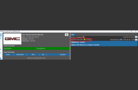
Technicians using the GM Service Information (SI) will soon find updated Removal/Installation and Replacement procedures (Fig. 1) with more detailed steps and fewer procedure links to other SI documents. The updated procedures have been optimized to only include the specific steps necessary to complete the repair. Many procedures may appear to be longer, but the added steps already existed in previously linked procedures.
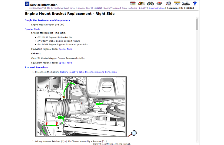 Fig. 1
The procedure links that remain in the Removal/Installation and Replacement procedures will be limited to content that contains steps that will always be performed, regardless of where they are used. Examples of these types of links include SIR Disable/Enable, Lifting and Jacking, Fuel Pressure Relief, and others.
The new authoring style is being implemented for the 2020 Cadillac CT4 and new or major vehicle program updates for the 2021 model year. Most existing vehicle programs will not be changed to the new style until the next major redesign of that particular model.
In addition to the updated service procedures, users will notice a few other changes that have been made to the Service Information. These changes in authoring style and content only affect Removal/Installation and Replacement procedures in SI. Other areas, such as Diagnostics and Schematics are not affected by these changes.
Single Use Fasteners and Components
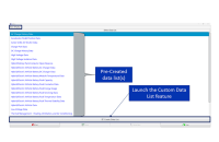
All procedures will begin with a list of all single use fasteners and components and the quantity required to complete the repair. (Fig. 2) The goal is to provide an initial list of replacement components that the technician will need to complete the repair and avoid repair delays.

Fig. 2
Enhanced Special Tool Lists
Special tool lists have always appeared in service procedures. Due to the change in authoring style, there will be an increase in the number of special tools used within certain service procedures. Because of the increase, the special tool list at the beginning of the procedure will be organized to show the subsection title and include the “Special Tools” link for the subsection where the tool originates. (Fig. 3)
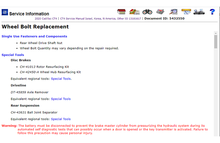 Fig. 3
Fastener Specifications
In the new authoring style, torque specifications have been removed from the service procedures. In place of the specifications, a link will appear to “Fastener Specification.” (Fig. 4) Previously, torque specifications appeared in the procedure and in the Fastener Specification table. Now, the specifications will only appear in the Fastener Specification table. The service procedures will include a link to the appropriate “Fastener Specifications” for the component being installed and tightened.
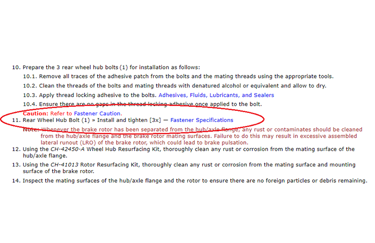 Fig. 4
Fastener Specification Tables
As part of the new authoring style, fastener specification tables are being changed to a visual format. With the addition of graphics, the tables will more clearly identify the location of the fasteners being tightened. (Fig. 5) Tightening sequence graphics have also been added. In most cases, the graphics will only include callouts for fasteners and components mentioned in the tables.
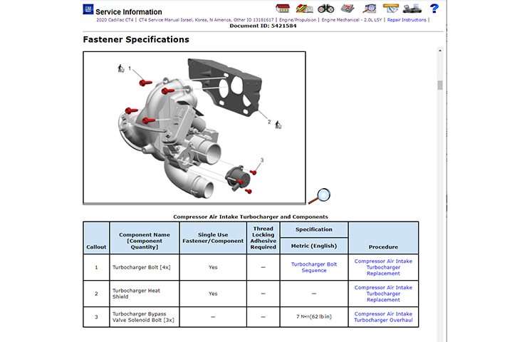 Fig. 5
Columns have been added to the table to indicate single use or the need for thread locking adhesive. The last column in the table will contain a link to the procedure where the component or fastener was first removed. (Fig. 6)
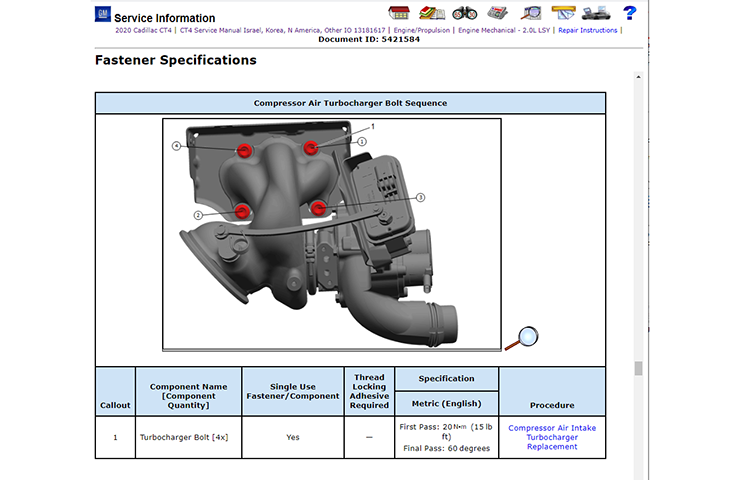 Fig. 6
Single Use Fastener and Component Identification
In current service procedures, single use fasteners and components are identified in the respective steps with the use of “Remove and DISCARD” and “Install NEW” in the text. They were also shown in specific tables within Fastener Specifications. In the new authoring style, the use of “Remove and DISCARD” and “Install NEW” text will continue, but two additional enhancements are being implemented.
As mentioned earlier, a list of “Single Use Fasteners and Components” will appear at the beginning of every procedure that includes components that require replacement. In addition, graphics that show the single use fastener or component will include a “trash can” icon next to the callout. The trash can will appear in the procedure and fastener table graphics. (Fig. 7)
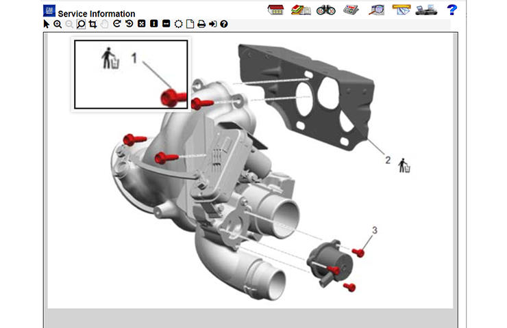 Fig. 7
– Thanks to Kevin Jakobiak


would also help if module number for instance K75 was in parts book, this would help prevent parts from ordering incorrect modules requested by technicians
In the updated procedures, GM focused on saving time for technicians by limiting the number of links within a procedure. Though linking directly to the Fastener Specifications seems to be counter to link reduction, it actually saves time and helps ensure the accuracy of the Service Information. Previously, procedures required clicking through multiple links to find a specification. Now, you will only need to click one link. As part of the updates, the group that handles service parts is aware of technicians’ concern for part packaging and is working on a viable solution. Unfortunately, a timeline of when the solution will be available has not yet been determined.
With regard to technician input. GM does include technicians in reviews of new concepts and frequently includes their recommended updates. Please continue to send in your feedback.
With the emphasis on saving time, why would you remove the torque specification from the service procedure? Now you have to click a link to get torque specs? The other changes being made makes some sense. But I agree with many here that the bolts and gaskets should be boxed together. Maybe you should consult with “Line Technicians” before making some changes to at least get their input, some of us have valuable insight.
Well I hope the graphics are a lot better than the preschool ones that are in Si now, along with better instructions on removing some things. Something more detailed instead of saying,( remove panel).
here is a very simple fix for all of this. Put the bolts in the box for what ever part needs to have hardware replaced. no reason to put notes in SI. Just Put a goodie bag full of hardware in with the part that is being replaced. I know that sounds too easy right?
The list of Single Use Fasteners and Components includes all components that will need to be replaced for the repair, including any applicable gaskets and seals.
Awesome idea. Like the list of single use fasteners and components. But I will still have to read entire procedure to find out what gaskets, seals, or sealers I need before I tell parts what to order. Why not include list of gaskets and seals. Heck if the new authoring style would include that techs might come close to the time allowance for the job.
This is a great idea, but why not list the part number with all the bolts that need replaced or just put them in the package with the component being replaced. Not all nomenclature between parts and service is the same which equates to the technician having to point out which bolt to the parts guy and wasting time.