
GM’s new Vehicle Intelligence Platform, or VIP, currently used on 2020-2022 Corvette, CT4, CT5 and 2021-2022 Tahoe, Suburban, Yukon, Escalade and Envision models, offers increased capacity and the ability to better manage technology complexity.
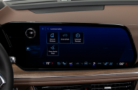
With a fivefold increase in system capacity and responsiveness over the current Global A system, the next-generation VIP electrical architecture offers the capability of managing over 100 computer modules. It’s able to support active safety systems, Over-the-Air (OTA) vehicle software updates, 5G networks, enhanced cybersecurity protections and EV technologies. (Fig. 1)
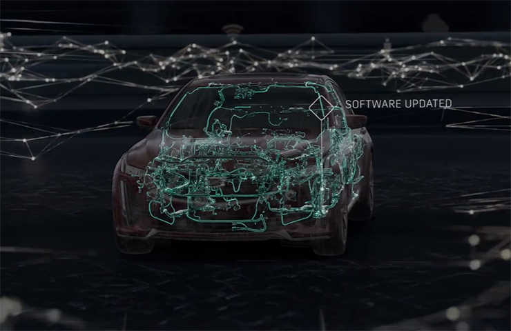 Fig. 1
The VIP electrical architecture includes two-wire CAN buses and two-wire Ethernet buses to ensure high speed data transfer and multiple single-wire LIN buses to exchange information between master control modules and other smart devices. Low speed General Motors Local Area Network (GMLAN) networks are no longer used in VIP vehicles.
CAN Protocol
The VIP architecture communication protocol is based on the widely used CAN (Controller Area Network) protocol. CAN buses are used where data needs to be exchanged at a high rate, primarily by a control device using the information to adjust a vehicle system, such as powertrain or body controls. Each CAN data network consists of two twisted wires, called CAN (+) and CAN (-), with a 120 ohm (Ω) termination resistor at each end of the bus between the CAN (+) and CAN (-) circuits.
Ethernet data communication technology uses a single twisted copper pair of wires at speeds of 100 Mbit/s and 1000 Mbit/s. The Ethernet system uses point-to-point communication that is connected via an Ethernet switch [Module <–> Switch <–> Module]. The Ethernet bus does not use terminating resistors.
The K56 Serial Data Gateway Module and the A11 Radio have an Ethernet switch that connects to other Ethernet modules. These modules communicate with other devices and systems in the vehicle via CAN and LIN buses. DTCs will be read on CAN to diagnose Ethernet, LIN, and system faults.
Any Ethernet harness failures should be repaired only using the appropriate kit to perform de-pin/re-pin overlays. In cases where the wiring harness repair kits are not available, the entire harness should be replaced. No crimps or splicing should be performed on the Ethernet wiring harness.
Serial Data Gateway
To signal any loss of communication and set DTCs, the K56 Serial Data Gateway Module must know and learn the control modules on the vehicle and their associated buses. If the Serial Data Gateway Module is replaced or another module is added to the bus, such as a dealer-installed accessary, a learn process must be done using the Serial Data Gateway Module learn procedure in SPS.
The learn process will not cause any previously learned contents to be forgotten or overwritten. If the learn process is not completed on a new Serial Data Gateway Module, DTC U1977 (ECU Identification Self Learn Not Completed) will be set until the learn procedure is performed. If the learn process is invalid due to internal malfunction or a Serial Data Gateway Module swap, DTC U3000 42 (Control Module – General Memory Failure) or DTC U3002 56 (Vehicle Identification Number – Invalid/Incompatible Configuration) will be set. The Serial Data Gateway Module will then lose communication with all control modules and set DTCs against control modules not on the vehicle.
The Serial Data Gateway Module also functions as a gateway to isolate the secure networks on the vehicle from unsecured networks. Isolating primary networks helps ensure advanced driver assistance systems and active safety features, such as enhanced collision avoidance, can all operate in conjunction with each other. If harmful software enters the vehicle through the infotainment system, OnStar, or the DLC, other vehicle systems may be affected.
Power Moding
In the VIP architecture, the K9 Body Control Module (BCM) is the Power Mode Master (PMM) and the K56 Serial Data Gateway Module is the back-up PMM. There are five power modes: Off, Accessory, Run/Service Mode (Engine Off), Propulsion (Engine On), and Start. As the PMM, the BCM uses a number of vehicle states and inputs to determine which power mode is required. It reports this information to other modules via serial data.
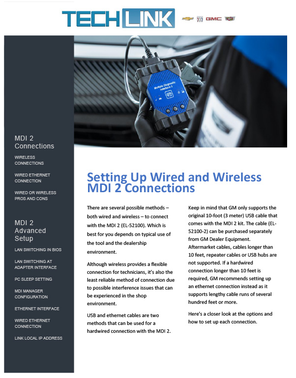
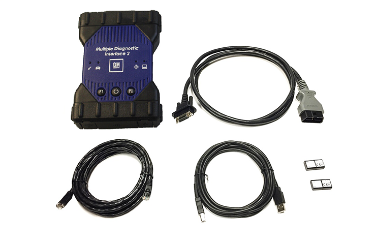
MDI 2 Required
The EL-52100 MDI 2 is required for control module programming, configuration and setup on vehicles equipped with the VIP architecture. The MDI 1 does not have the capability to complete programming and setup procedures. Using an MDI 1 on these vehicles could result in erroneous data or failed programming events that could lead to unnecessary module replacement.
When a scan tool is installed, it will attempt to communicate with every control module that may be available on the vehicle, depending on optional equipment. If an option is not installed on the vehicle, the tool will display No Communication for that control module. In order to avoid misdiagnosis of a No Communication message, refer to the Data Link References that lists the control modules and the buses with which the modules communicate in the appropriate Service Information and the vehicle build RPO codes to determine optional control modules.
Programming a Module
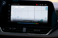
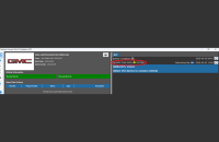
When SPS (Service Programming System) programming a module (Fig. 2), follow all SPS on-screen instructions.
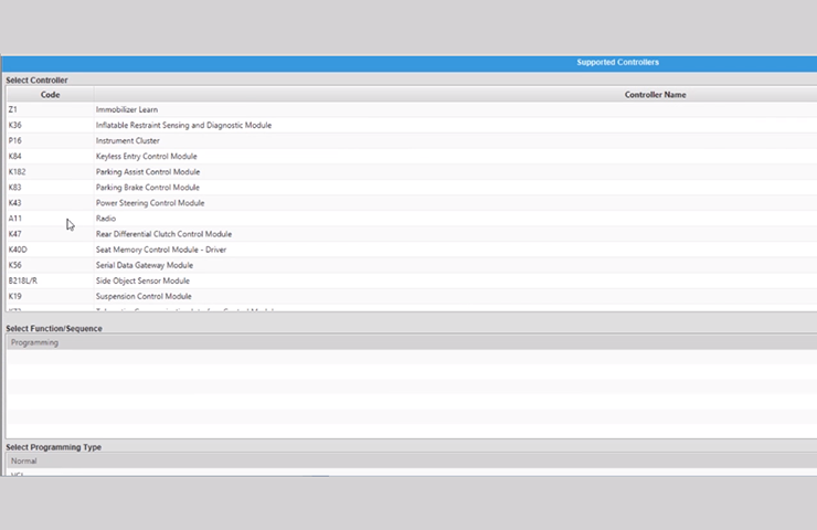 Fig. 2
These tips also should will help in successful programming:
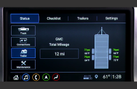
Confirm the VIN – Techline Connect (TLC) does not automatically execute the Vehicle Identification Number (VIN) Read with the power mode Off. Technicians must confirm that the VIN is correctly identified prior to programming by verifying the VIN reflected in Techline Connect matches the VIN plate on the vehicle. (Fig. 3) Be sure not to select a VIN that is already in the Techline Connect application memory from a previous vehicle.
To use the VIN Read when using Techline Connect, the vehicle’s power mode (ignition) must be On before reading the VIN from the vehicle’s Engine Control Module (ECM), which is the vehicle’s VIN master module. Programming or reprogramming modules with the incorrect VIN and using software and calibration files from incorrect VINs can cause future serviceability issues as well as potential vehicle performance issues that may require the vehicle to be reprogrammed again.
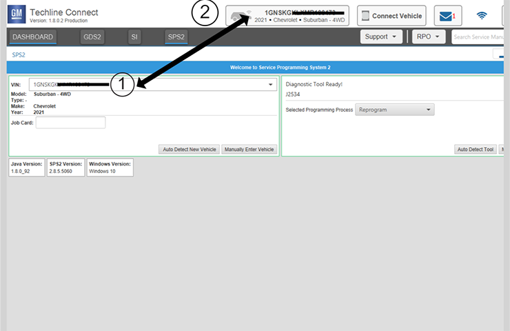 Fig. 3
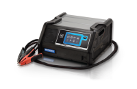
Battery Voltage – Stable battery voltage is critical during programming. Any fluctuation, spiking, over voltage or loss of voltage will interrupt programming. Install a GM Authorized Programming Support Tool to maintain system voltage. Do not use a battery charger.
Power Mode Off – The power mode (ignition) must be Off to begin module programming. Any load on the vehicle’s battery, such as interior lights, exterior lights and Daytime Running Lamps, and HVAC operation, may affect the download process and may cause errors to occur.
Do Not Change the Power Mode – Do not change the power mode of the vehicle (position of the ignition switch) during the programming procedure unless instructed to do so. Programming will direct the appropriate control module(s) to change power mode as needed during the procedure, independent of the vehicle’s power mode.
Keep Vehicle Fully Asleep – Ensure that the vehicle will not become awake during the programming event by keeping all doors closed (vehicle fully asleep). For access to the vehicle, trip the driver’s door latch to the closed position so that the door can remain open. If a closed door is opened during programming, buses will wake up and cause error codes to set
Clear All DTCs – After programming, clear all DTCs and allow the vehicle to go into sleep mode. DTCs U1962 (Unable to Authenticate Serial Data Message) and U1983 (Serial Data Gateway Module Security Hardware Internal Malfunction) may set and the Check Engine MIL may illuminate if the DTCs are not cleared and the vehicle does not go to sleep after programming or Serial Data Authentication Configuration (SDAC).
If SDAC fails, DTC U1962 will set as a current DTC. It will not clear until another programming event occurs that runs SDAC, or the standalone SDAC procedure is performed using SPS. If DTC U1962 is stored only as a history DTC and not retrieved as a current DTC, do not perform the SDAC procedure.
Wait 5 Minutes – After programming, let the vehicle sit for five minutes with the ignition Off, Retained Accessory Power Off and the key fob removed from the vehicle after completing programming. After five minutes, the system can be operated to verify repairs.
– Thanks to Bret Raupp and Peter Shear


