
Seal installation depth is critical when replacing the transfer case input seal. On some 2020-2021 Silverado 2500HD/3500HD and Sierra 2500HD/3500HD trucks equipped with the 10L1000 10-speed automatic transmission (RPO MGM, MGU) and the RPO NQF or NQH transfer case, the DT-50648-A Seal Installer may not install the input seal to the correct depth.
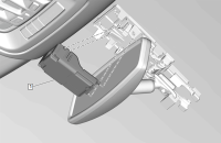
There is a gap around the outer portion of the seal that needs to be centered over a weep hole in the transfer case. The weep hole is drilled in the center of a groove machined into the case. (Fig. 13) The DT-50648-A Seal Installer will not work for these applications.
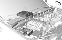
![]() Fig. 13
Fig. 13
There are two transfer case front case designs. The seals install at different depths for design 1 and design 2. To identify each design, look for a machined groove where the seal is installed (circled as shown). If there is a defined machined groove in the case, it is a first design case. (Fig. 14)
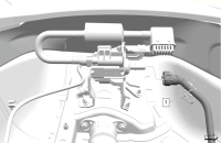
![]() Fig. 14
Fig. 14
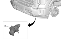
If there is not a defined groove machined into the case, it is a second design case. (Fig. 15)
![]() Fig. 15
Fig. 15
While a service tool strategy is being developed, use the J-45228 Pinion Bearing Cup Replacer to drive the seal in the case. (Fig. 16) However, there is no stop at the correct depth when using the J-45228 tool. The seal must be driven in slowly during installation and checked for the correct depth. Be careful not to drive the seal in too deep or it will be necessary to replace the seal again.
![]() Fig. 16
Fig. 16
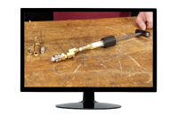
Before installation, determine the case design and put a mark on the outside of J-45228 tool to use as a visual aid for the correct seal depth. (Fig. 17) When the mark is even with the case, stop installing the seal. For first design cases, mark the tool at 17 mm, and for second design cases, mark the tool at 19.5 mm.
![]() Fig. 17
Fig. 17
After installation, verify the correctly installed depth by using a vernier caliper to check the distance between the case and the outer part of the seal. (Fig. 18) On the first design case, the dimension should be 1 is 10 mm, and on the second design case, it should be 2 is 13 mm.
![]() Fig. 18
Fig. 18
Refer to Bulletin #PIP5810 for additional information.
– Thanks to Steve Schipansky


