
The 2022 GMC HUMMER EV Pickup Edition 1 features a number of standard accessories, including assist steps, recovery hooks and a soft roll-up tonneau cover. (Fig. 1) There also are a number of additional dealer-installed accessories available for the HUMMER EV Pickup that can help enhance functionality and convenience.
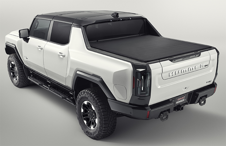 Fig. 1
Note: Preproduction model with available features shown. Actual production models may vary. Due to current supply-chain shortages, certain features shown have limited or late availability, or are no longer available.
Here are a few tips to follow to ensure proper operation when installing some of the available accessories on the HUMMER EV Pickup. Always refer to the appropriate Service Information (SI) when installing GM Accessories.
Accessory Touchscreen Control Switches
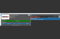
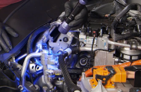
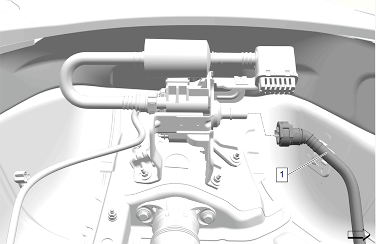
The accessory touchscreen control switches that operate added electrical components require installation of the Battery Distribution Engine Compartment Fuse Block Package (SI Doc. ID 5775311). (Fig. 2)
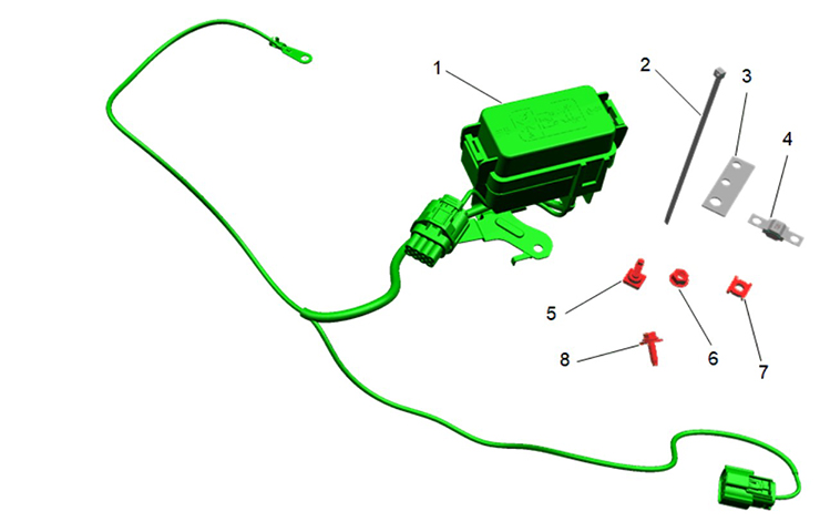 Fig. 2
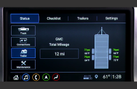
Perform the auxiliary screen setup on the infotainment screen with the customer in the truck upon delivery. (Fig. 3) If the truck is in Demo mode, the name and icon, and the name saved to the aux card, on the center stack will not be saved after the start/stop cycle.
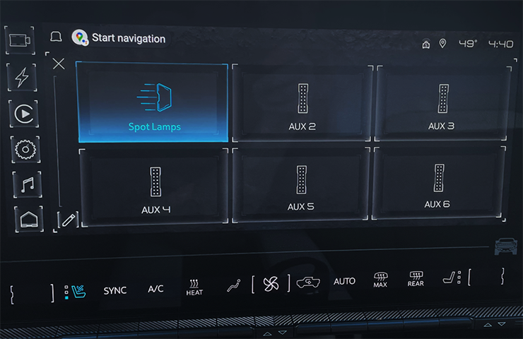 Fig. 3
Rear Aero Panel When Installing Rear Cargo Lamp Accessory Kit
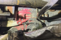
When removing the rear aero panel, there are several hidden fasteners that are accessed through a 1/4-inch diameter hole at the bottom flange of the rear fascia. After removing all the exposed Torx screws, gently pull down the rear fascia while loosening the 6 hidden Torx screws. (Fig. 4) With the screws loosened, pull down the rear fascia to create a gap large enough to completely remove the hidden Torx screws. Shown are the 3 hidden screws on the left-hand side. (Fig. 5)
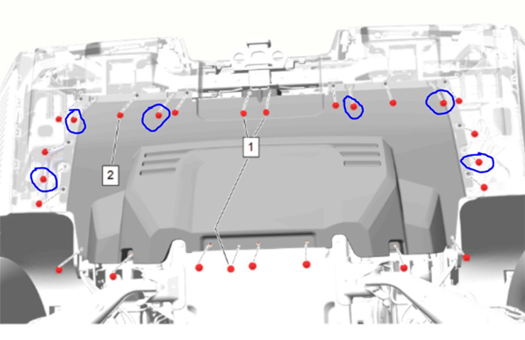 Fig. 4
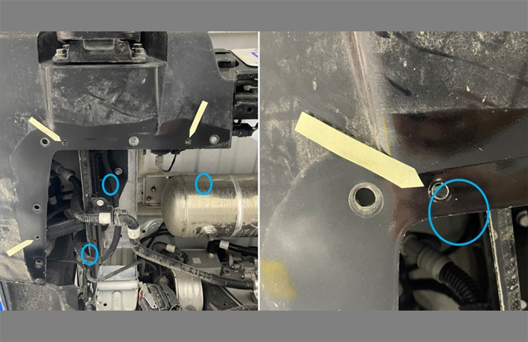 Fig. 5
Outside Rearview Mirror Projection Lights
Service Information instructions have been updated for the Outside Rearview Mirror Projection Lights (SI Doc. ID 5838676).
When removing the mirror glass, apply pressure inward at the top of the outside rearview mirror glass until full travel is reached. Use a plastic flat-bladed trim tool and a curved pick tool to help release the mirror glass from the mirror actuator. (Fig. 6)
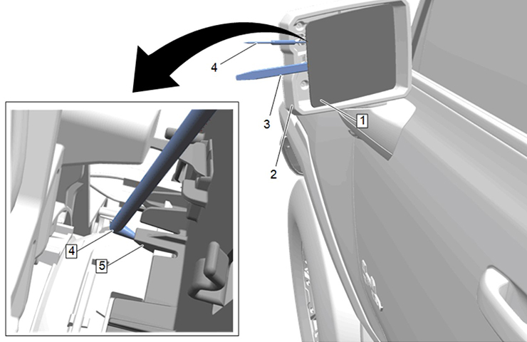 Fig. 6
Before installing the new mirror lamp attachment, check the part label to ensure correct orientation (left-hand or right-hand).
Tailgate Step Lighting
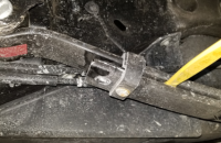
The Cargo Lamp Kit includes tailgate step lighting (SI Doc. ID 5783067). During installation, the 2-way connector on the supplied jumper harness in the accessory kit must be modified by swapping the wires in the connector (step #18). (Fig. 7) Remove black wire terminal (circuit 2050) from cavity 1 and remove white wire terminal (circuit 7762) from cavity 2. Insert the previously removed white wire terminal into cavity 1 and insert the previously removed black wire terminal into cavity 2. Make sure terminals are locked into the connector.
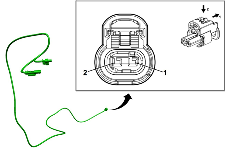 Fig. 7
The 2-way connector is located under the truck and plugs into the remaining tailgate lighting accessory harness. (Fig. 8) The kit will be updated and SI will be revised once the modification is no longer needed during installation.
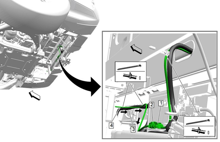 Fig. 8
Interior Ambient Footwell Lighting
The accessory wiring harness instructions have been updated for installing the Front Floor Illumination Lamp Package (SI Doc. ID 5841494).
In cavity 1 of BCM connector X2 (light pink connector), remove the gray wire using the J-38125-215A Terminal Release Tool and insert the yellow wire from the accessory harness (step #12). Cut the terminal from the gray wire coming out of cavity 1, remove some insulation and splice with the open-end Dura-seal splice joint present in the harness. Fold back and tape the violet wires from the accessory harness. It is not used. (Fig. 9)
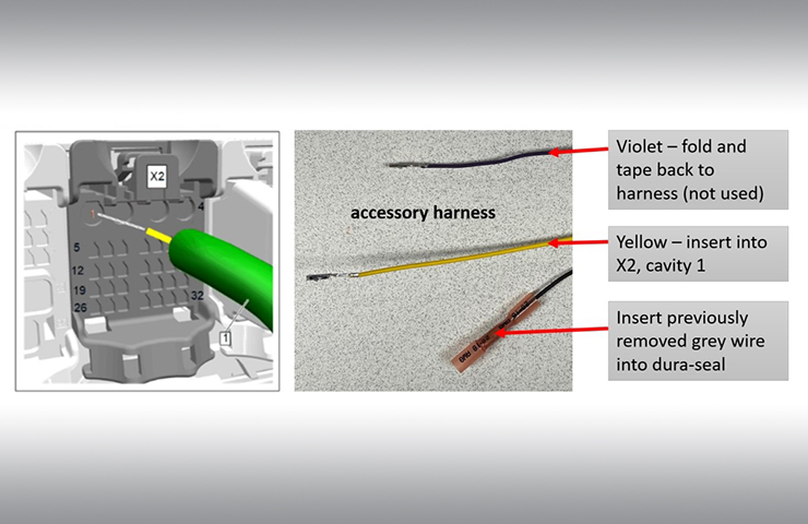 Fig. 9
Front Off-Road Auxiliary Lights
When installing the front off-road auxiliary lights in the Spot Lamp Kit (SI Doc. ID 5905055), a hole must be drilled on the underside of each fender ornamentation vent (step #4). There is a dimple approximately 23mm from the heat stake patch on the panel where the pilot hole should be drilled. Be sure to locate the correct dimple before drilling. The dimple may be covered by a yellow decal. (Fig. 10)
 Fig. 10
Hard Power-Retractable Tonneau Cover
The Pickup Box Cover Package (SI Doc. ID 5766441) for the hard power-retractable tonneau cover requires using a shim kit for correct tonneau rail position. If the shims are not installed, the side rail on the power tonneau may spread too far apart and not allow the cover to contact the position switches at the end of the rail. Shims are typically required at the rear-most screw of the lower rail on the passenger side between the extrusion and the bed cap. (Fig. 11) Refer to #PIT5898 for more information.
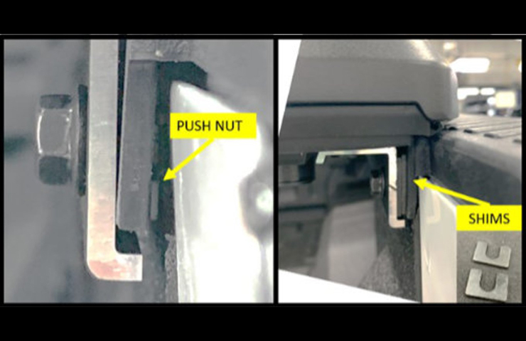 Fig. 11
To secure the lower side rail, it’s necessary to drill a 16mm hole through the plastic bed cap (step #8). (Fig. 12) The front hole of the side rail does not have a metal surface to secure the bolt. The hole will allow the bolt head to mate to the side rail and not the plastic bed cap, which will help prevent potential torque loss.
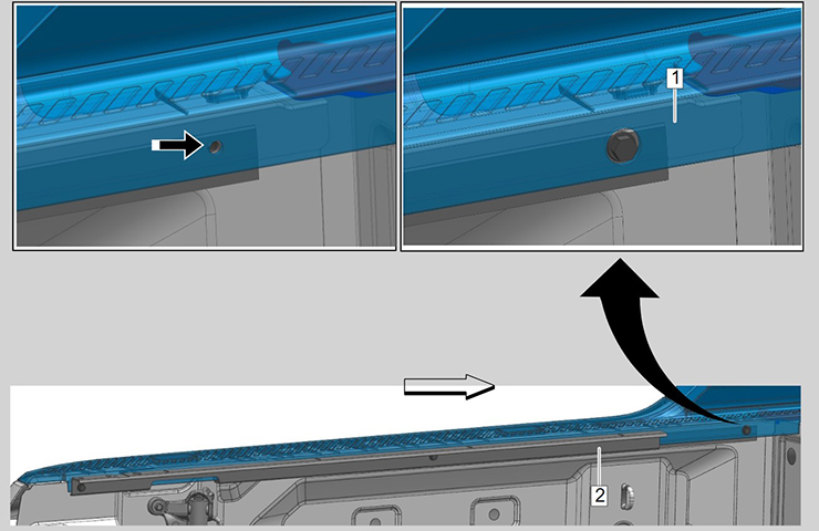 Fig. 12
When loading the tonneau assembly into the bed, add protective tape on the sail panel trim to avoid any potential damage. (Fig. 13)
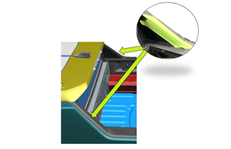 Fig. 13
Once the tonneau cover is installed, follow the calibration procedure. Make sure the vehicle is unlocked and the driver’s door is open.
The cover must be fully retracted (open) at the start of calibration. (Fig. 14) Failing to fully retract the cover will result in a jammed clutch, which can be difficult to release.
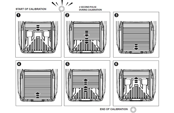 Fig. 14
If the cover fails the initial calibration, push the manual release button, fully retract (open) the cover, pull the release button to lock the clutch and try the calibration again.
A failed calibration indicates the shims are needed because the rear limit switches are not seeing the cover. Refer to #PIT5898.
For additional tonneau cover troubleshooting tips on operation and performance, refer to SI Doc. ID 5766441.
– Thanks to Scott Lewiston and Mark Shearer


There’s nothing quite like using a hole saw to drill big holes in a $120,000 vehicle. That rear cover is not friendly, The hidden screws will get left out in the real world eventually. I had a nice time working with the FSE on these when they came in. Little behind the scenes experience.