
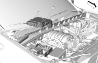
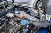
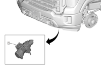
The 2025 Envista, Encore GX, Trax and Trailblazer are available with the new 1.2L engine (RPO LBP). The engine configuration features E85 compatibility, which required an update to the Evaporative Emission System (EVAP) system. The system includes a new component — the G34 EVAP Leak Detection Pump Assembly (Fig. 7, #7)— that replaces the vent solenoid in traditional EVAP systems.
 Fig. 7
G34 EVAP Leak Detection Pump
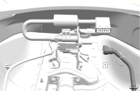
The G34 EVAP Leak Detection Pump (Fig. 8) on the 1.2L engine is used for fuel tank pressure sensor correlation and leak checking the EVAP system for small and large system leaks. It is critical to disconnect this pump before performing leak diagnostics to prevent permanent damage.
 Fig. 8
Failure to follow the correct service procedures will require pump replacement since the EVAP leak detection pump is highly susceptible to damage if exposed to smoke or mineral oil used in OEM and aftermarket smoke testers.
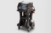
Using the necessary special tools, including the GE-41413-A / B / C Evaporative Emissions System Tester (EEST), the updated leak diagnostic procedures for DTCs P0442 (Evaporative Emission System Small Leak Detected) and P0455 (Evaporative Emission System Large Leak Detected) instruct technicians to disconnect the leak detection pump from the EVAP system before testing. Refer to Document ID 6496657 in the appropriate Service Information for vehicle-specific instructions.
TIP: If smoke from a leak test enters the G34 EVAP Leak Detection Pump, it will cause premature failure, requiring full replacement.
How the G34 Leak Detection Pump Works
The component is used to detect leaks in the EVAP system and diagnosing DTC P0442 and P0455. Unlike traditional EVAP systems, it does not use a vent solenoid to seal the system, which significantly changes the procedure for performing leak tests.
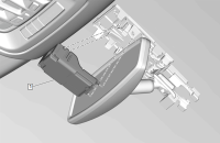
The G34 EVAP Leak Detection Pump Assembly consists of four main components. (Fig. 9)
 Fig. 9
- EVAP vacuum leak pump switching valve
- Reference orifice (0.017-inch, 0.4 mm, in size)
- EVAP vacuum leak pump pressure sensor
- Leak detection pump (driven by a brushless 12V DC motor)
These components are integral parts of the EVAP leak detection pump assembly and are not serviceable.
Leak Detection Process
Here is the updated procedure the ECM will perform to run DTC P0422 and P0455 diagnostics and detect leaks on the new 1.2L LBP engine.
- The vehicle must be driven at least 0.1 miles and then turned off for 5 – 5 hours in ambient temperatures above 40°F (4.5°C).
- The system will begin its automated leak test between 5 – 5 hours when the Engine Coolant Temperature (ECT) stabilizes with ambient temperature.
- The switching valve (#1) actuates, and the pump (#4) pulls a vacuum over the reference orifice (#2) to establish a baseline measurement.
- The valve then switches, allowing the pump to pull a vacuum on the entire EVAP system.
The test runs for up to 800 seconds, comparing pressure values to determine if a leak exists.
Differences from Traditional EVAP Systems
The new EVAP system has several different features than that of a traditional system.
| Feature | Traditional EVAP System | New G34 EVAP System |
| Vent Solenoid | Used to seal the system | Not used in this system |
| Leak Detection Method | Engine Off Natural Vacuum (EONV) | G34 pump actively pulls vacuum |
| Smoke Test Procedure | Introduce smoke at purge solenoid | Introduce smoke at the canister line (NOT through G34 pump!) |
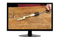
Performing a Smoke Test on the G34 EVAP System
To perform a smoke test of the new EVAP system:
- Locate the right rear-wheel well where the G34 pump is installed.
- Disconnect the vapor line connecting the EVAP canister to the G34 pump.
- Attach the EVAP adapter at the disconnection point.
- Introduce smoke at this location – NOT through the G34 pump. (Fig. 10)
- Perform the smoke test as usual.
- Reconnect the vapor line securely after testing.
 Fig. 10
TIP: Do not introduce smoke through the G34 pump. It will allow mineral oil contamination, which will lead to pump failure and replacement.
For more details about the new EVAP system, refer to the EVAP System Description, Document ID 6496626, in the appropriate Service Information.
– Thanks to Marco Salcedo and Kyle Mortensen


