Acting as the interface between the operator of the climate controls and the HVAC system, the Body Control Module (BCM) maintains and controls the desired air temperature and air distribution settings in the cabin and provides blower, air delivery mode and air temperature control. (Fig. 1)
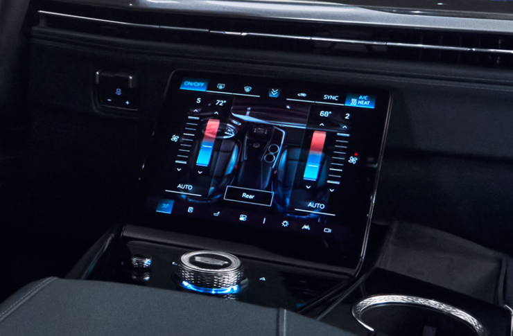
Fig. 1
HVAC is the tenth topic in the TechLink series highlighting several of the related systems handled by the Body Control Module (BCM) on GM models built with the Vehicle Intelligence Platform (VIP). The goal of this series is to help improve understanding of the components operated by the BCM and reduce warranty claims and unnecessary component replacement.
The earlier systems in the series are the Keyless Entry System, Content Theft Deterrent, Door Latch Actuators, Tire Pressure Monitoring Systems, Exterior and Interior Lighting, Fixed and Moveable Windows, Mirrors, Wipers and Washers and Horns and Pedestrian Alerts.
COMPONENT BREAKDOWN
- Body Control Module
- Radio control assembly
- Front and rear HVAC controls
- Front and rear blower motors
- Blower Motor Control Module
- Air Temperature, Mode and Recirculation actuators
- Evaporator temperature sensor
- A/C refrigerant pressure sensor
- Sun load and passenger-compartment temperature sensor
- Windshield moisture, temperature and humidity sensor (if equipped)
- A/C compressor and compressor solenoid
- Auxiliary electric air heater (if equipped)
HVAC SYSTEM OVERVIEW
The heating and air conditioning system provides heated and cooled air to the passenger compartment. The A/C system also removes humidity and helps reduce windshield fogging.
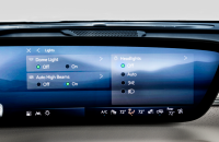
The radio control assembly contains the information display and touchscreen and serves as the interface between the vehicle and the front HVAC controls. Control inputs, indicators and backlighting are exchanged through dedicated circuits. Selected HVAC values are passed to the BCM via serial data.
The front HVAC controls contain the switches and knobs used to control the primary HVAC functions. The rear HVAC controls provide switches, buttons and dials used for rear temperature, airflow and blower requests. (Fig. 2)
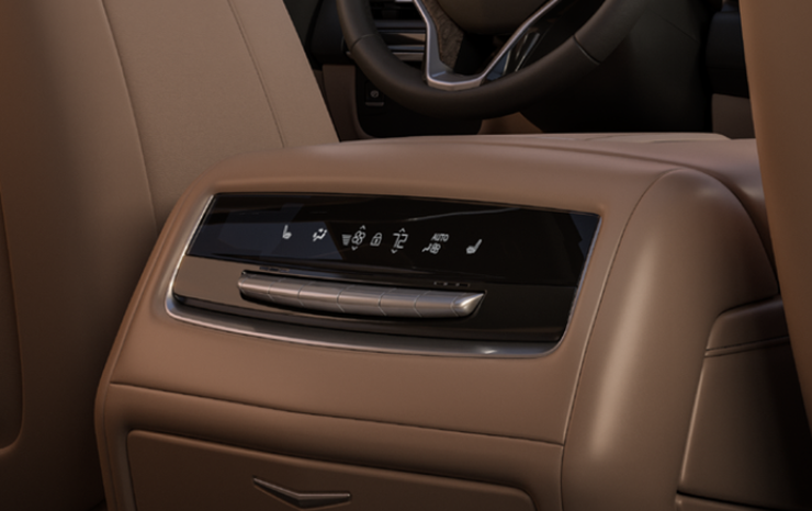
Fig. 2
The BCM controls the HVAC actuators through the LIN bus. Internal stepper motors move the temperature, mode and recirculation doors to the commanded positions. It also controls the blower motor and requests activation of the compressor from the Engine Control Module (ECM).
TIP: Under certain conditions, the system sets itself to 76 degrees with the defrost function set on High. This issue is related to the VCU/radio, not the BCM. When the BCM is not receiving instructions from the VCU/radio, whether the cause is an issue in the VCU itself, or in the communication line between the two, the BCM will instruct the HVAC system to default to this state.
COMPONENT OPERATION
Temperature Control and Sensors
The temperature actuators move the mixed-air doors. When needed, more air is directed through the heater core for heat, and more air is directed through the evaporator core for cooling.
Physical duct-air temperature sensors are not used. The BCM calculates duct-air temperature using engine coolant temperature, coolant flow, evaporator temperature, outside air temperature, solar load, blower speed, air-inlet door position and temperature-door position.
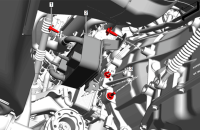
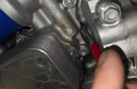
The evaporator temperature sensor (Fig. 3) measures the air leaving the evaporator. The HVAC software uses this value to determine a target evaporator temperature and adjust compressor operation.
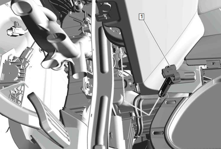
Fig. 3
The refrigerant pressure sensor provides pressure information to the ECM. If pressure is too high or too low, the ECM will not allow the compressor clutch to engage.
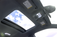
The sun load and passenger-compartment temperature sensor (Fig. 4) allows the system to compensate for heat entering the vehicle from sunlight and changes in cabin temperature.
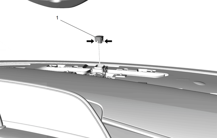
Fig. 4
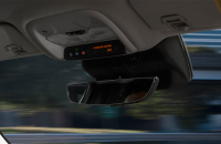
If equipped, the windshield moisture, temperature and humidity sensor (Fig. 5) provides information used to calculate fog risk. The BCM may activate the A/C and defrost functions, reduce compressor output or use partial recirculation to improve warm-up conditions without increasing windshield moisture.
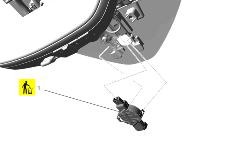
Fig. 5
Blower Motor Operation
The selected blower speed setting is sent to the BCM via serial data. A speed-feedback signal is returned to the BCM for monitoring. (Fig. 6)
The rear blower function can be selected from the front or rear HVAC controls. The Blower Motor Control Module changes the ground-side voltage drop to adjust rear blower speed.
Blower feedback also helps the vehicle manage engine coolant flow for occupant comfort and windshield defrosting while allowing the ECM to optimize fuel economy and emissions.
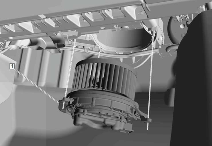
Fig. 6
A/C Compressor Operation
When the A/C or AUTO switch is pressed, the HVAC controls send an A/C request to the BCM. The BCM sends the request to the ECM over the CAN bus.
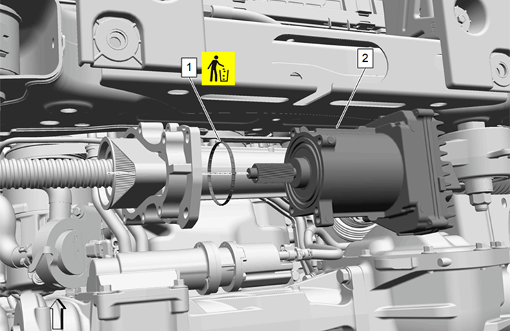
The ECM checks the required preconditions and, if they are met, sends a release signal back to the BCM. The BCM then activates the compressor, and controls compressor performance through the compressor solenoid. (Fig. 7) Compressor performance is regulated using evaporator temperature and multiple engine statuses. Refer to the Automatic HVAC Description and Operation in the appropriate Service Information to see a complete list of preconditions from the ECM.
The A/C indicator shows that the air conditioning function has been requested. It does not confirm that the compressor is continuously active.
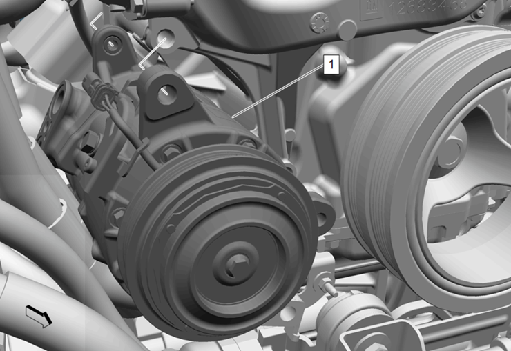
Fig. 7
Air Delivery, Defrost and Recirculation
The desired air distribution mode can be selected with the air distribution switches at the HVAC control or on the display touch screen, if present. The HVAC control delivers the values to the BCM via the radio/VCU as a passthrough. The BCM then moves the mode doors to the required position. Depending on the position of the door, air is distributed through various ducts leading to the outlets in the vehicle.
When defrost is active, the BCM commands outside-air operation to help reduce windshield fogging. The blower operates in defrost mode regardless of coolant temperature, and A/C operation is available in all modes.
In recirculation mode, the recirculation door blocks outside air and circulates cabin air.
In outside-air mode, the door routes outside air into the vehicle. Recirculation is not available while the defrost mode is active.
During automatic operation, partial recirculation may be used to improve heating or cooling performance and reduce energy use. The recirculation indicator may remain illuminated during this operation.
Automatic Operation
In automatic mode, the BCM controls the compressor, blower motors, temperature actuators, mode actuators and recirculation actuator to maintain the selected cabin temperature.
To enter full automatic operation, activate the AUTO switch and do not set the temperature to full hot or full cold. Changing an individual setting other than temperature places that function in manual control; the remaining functions stay under automatic control until changed. (Fig. 8)
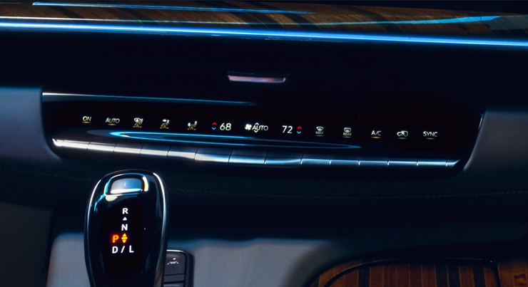
Fig. 8
The BCM monitors outside-air temperature, passenger-compartment temperature, calculated duct-air temperature, evaporator temperature, sun load and windshield moisture information, if equipped.
Auxiliary Electric Heat and Afterblow
Some models use an auxiliary electric heater to provide heat before the engine coolant reaches normal operating temperature. The heater is a 12-volt positive-temperature-coefficient element located downstream of the heater core.
Check the appropriate Service Information for the outside temperature and engine coolant temperature required for operation. The temperature blend door must be commanded to the full hot setting.
Afterblow operates the blower after the engine is turned off under certain conditions to dry the evaporator core and reduce microbial growth that can cause unwanted odors. It is not always enabled on vehicles and may need to be enabled using a scan tool if odor problems are present.
For additional details, refer to HVAC > HVAC – Automatic in the appropriate Service Information.
– Thanks to Andrew Howley