
Damage to electrical terminals can lead to inaccurate test results, difficult diagnosis and system failures. When servicing a suspected wire/terminal issue, be sure to check for the following conditions:
- Any signs of connector damage
- Excessive wear to the terminal locking mechanism
- Loose or backed out terminals
- Damaged terminated lead due to improper probing tool use
Most intermittent conditions are caused by a faulty electrical connection or wiring. Look for loose or corroded terminals, poor connections between the male and female terminal at a connector, a terminal not seated all the way into the connector body, and poor terminal to wire connection, such as poor crimps and corrosion.
Terminal Tools
There are several special tools that can be used for diagnosis, testing and removal of terminals. (Fig. 1) Keep in mind that the kit and tool numbers may change as they are updated by the supplier.
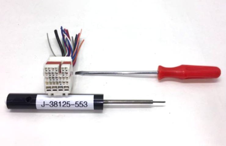 Fig. 1
Terminal Test Probes
The J-35616-F Terminal Test Probe Kit includes probes that are sized to fit the various terminal sizes and their shapes properly. (Fig. 2) There are also several smaller kits available.
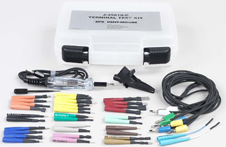 Fig. 2
Terminals are becoming increasingly smaller and more complex in design. Using an improper test kit probe may cause damage to the terminals being probed and result in false readings during a diagnostic procedure. Using an instrument other than the correct probe will, in most cases, cause irreversible damage to the terminal by enlarging or deforming it to the point that it will no longer mate correctly.
TIP: Check the Test Adapter and Description Table when selecting the correct test adapter for front probing connectors. Refer to Power and Signal Distribution > Wiring Systems and Power Management > Diagnostic Information and Procedures > Probing Electrical Connectors in the appropriate Service Information SI.
Do not visually choose the terminal test adapter because some connector terminal cavities may appear larger than the actual terminal in the cavity. Using a larger terminal test adapter will damage the terminal.
Terminal Release Tools
The J-38125-580 Terminal Release Tool Kit contains various tools designed to release terminals from the connector. The terminals have a metal arm or tang that locks into the connector body. (Fig 3)
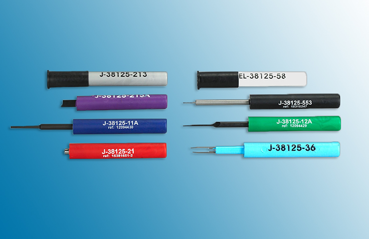 Fig. 3
When the release tool is inserted into the canal, it moves the tang against the terminal, which allows the connector body to be released and moved outward. Tangless terminals are released in a similar fashion with the tool pushing the arm of the connector body to release the terminal.
Splice Sleeve Crimping Tools
Splice sleeve crimping tools are part of the process necessary for repairing terminals and connectors. The Service Information contains the necessary information for crimp nest selection. Crimp nest selection is determined based on wire size and is critical to splice crimp quality.
Proper Terminal Contact
Test terminal contact at the component and any inline connectors before replacing a component. A poor connection between the male and female mating terminals at a connector may be the result of contamination or deformation.
Contamination may result if the connector halves are improperly connected. Contamination also may be caused by a missing or damaged connector seal, damage to the connector itself, or terminal exposure to moisture and dirt. Contamination, usually in the underhood or underbody connectors, leads to terminal corrosion and, eventually, an open circuit or intermittently open circuit.
Deformation is caused by probing the mating side of a connector terminal without the proper adapter. Other causes of terminal deformation are improperly joining the connector halves, or repeatedly separating and joining the connector halves. Deformation, usually to the female terminal contact tang, can lead to poor terminal contact and an open or intermittently open circuit.
Probing Electrical Connectors
Connectors with 0.50 terminals should not be probed within the female terminal. There is a test point on the connector next to the terminal where testing should be performed.
When front probing a connector, disconnect the connector and insert the appropriate test adapter straight into the terminal on the mating side (front) of the connector. Refer to the appropriate Connector End View in the Service Information to determine the correct test adapter for front probing terminals.
When back probing a connector when instructed in a diagnostic procedure, disconnect the connector and insert the back probe test lead into the back of the terminal, between the terminal and the connector body. Do not back probe sealed connectors.
Measure the resistance between the back probe test lead and the corresponding terminal on the front of the connector to ensure a good connection was made. If excessive resistance is found, reposition the back probe test lead to ensure good contact between the back probe test lead and the terminal.
Connect the electrical connector with the back probe test lead installed and continue diagnosis.
Testing Terminal Contact in Bussed Electrical Centers
Be sure to use the correct test adapter when testing for proper terminal contact of fuses and relays in a bussed electrical center.
First, separate the connector halves and visually inspect for contamination, such as a white or green build-up within the connector body or between terminals, which causes high terminal resistance, intermittent contact, or an open circuit. An underhood or underbody connector that shows signs of contamination should be replaced in its entirety, including the terminals, seals, and connector body.
Next, use an equivalent male terminal/terminated lead to verify that the retention force is significantly different between a known good terminal and the suspect terminal. Replace the female terminal if contact is suspect.
Flat Wire Connectors
There are not any serviceable parts for flat wire connectors on the harness side or the component side. To test terminal contact, remove the component and visually inspect each side of the connector for signs of contamination. Avoid touching either side of the connector as oil from your skin may be a source of contamination as well.
Also inspect the terminal bearing surfaces of the flat wire circuits for splits, cracks, or other imperfections that could cause poor terminal contact. Check that all of the terminals are uniform and free of damage or deformation on the component side connector. Insert the appropriate adapter into the flat wire harness connector in order to test the circuit in question.
Terminal Fretting
Some intermittent conditions can be caused by wire terminal fretting corrosion. Fretting corrosion is a build-up of insulating, oxidized wear debris that can form when there is small motion between electrical contacts. The oxidized wear debris can pile up enough at the electrical contact spots that the electrical resistance across the connection increases. Movement between the contacting surfaces as small as 10 to 100 microns can cause fretting. To put this in perspective, a sheet of paper is about 100 microns thick, so fretting motion is small and hard to see.
Vibration and thermal expansion/contraction are the main sources that create fretting motion. Since vehicles vibrate and can experience large temperature swings, they are a good source for fretting motion. Tin, copper, nickel, and iron surfaces are all susceptible to fretting corrosion. Although it may be difficult to see, fretting corrosion looks like small, dark smudges on the contact surface of the terminals.
To correct a fretting condition, disconnect the suspect connector and add dielectric grease/lubricant (Nyogel 760G or equivalent, meeting GM specification 9986087) to both sides of the connector terminals. Reconnect the connector and wipe away any excess lubricant. The dielectric grease will correct the additional terminal contact resistance due to the fretting corrosion.
TIP: Not all connections are susceptible to fretting corrosion. Do not apply dielectric grease to gold-plated terminals, such as squib connectors, coax terminals or high voltage cable connections.
– Thanks to Scott Cartwright and Peter Joslyn


Great info
Good stuff