
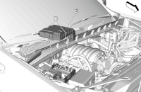
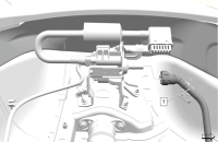
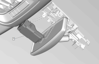
Some 2020-2024 Silverado 1500, Silverado 2500HD/3500HD, Sierra 1500, Sierra 2500HD/3500HD; 2021-2024 Tahoe, Suburban, Yukon and Escalade models equipped with the 3.0L diesel engine (RPO LZ0, LM2) or 6.6L diesel engine (RPO L5P) may have an illuminated Check Engine MIL, a Service Emissions System message displayed on the Driver Information Center and DTCs P249C (Excessive Time To Enter Closed Loop Reductant Injection Control) and/or P20E8 (Reductant Low Pressure) set in the Engine Control Module. These conditions may be caused by a disconnected or damaged Emission Reduction Fluid (Diesel Exhaust Fluid) Exhaust Front Pipe Injector Supply Pipe. (Fig. 1)
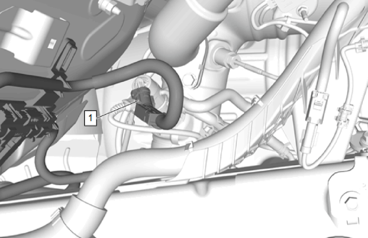
Fig. 1
TIP: If DTCs P249C and/or P20E8 have set after the installation of a new Emission Reduction Fluid Pump/Tank, refer to Emission Reduction Fluid Pump Priming in the appropriate Service Information.
If DTCs P249C and/or P20E8 are set, it may be necessary to perform a cleaning procedure and check for crystallized Diesel Exhaust Fluid (DEF) at the supply pipe connector.
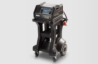
First, perform a Reductant System Leak Test. If there is a leak at the Emission Reduction Fluid Exhaust Front Pipe Injector Supply Pipe or at the connection to the Reductant Fluid Injector or the Emission Reduction Fluid Pump Outlet Port, check for any damage to the supply pipe or connector. (Fig. 2)
If the supply pipe or connector is damaged, replace the Emission Reduction Fluid Exhaust Front Pipe Injector Supply Pipe and perform a Reductant System Tamper Service Bay Test.
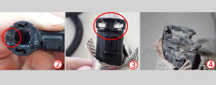
Fig. 2
If there is not any damage, a connector cleaning procedure should be performed. Crystallized DEF may have formed, which may not allow the pipe to properly seat on the injector and lead to a possible leak.
Cleaning Procedure
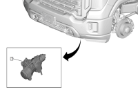
If the Emission Reduction Fluid Exhaust Front Pipe Injector Supply Pipe is contaminated with crystallized DEF in or around the connector (Fig. 3), perform the cleaning procedure before attempting to reconnect the supply pipe to the Reductant Fluid Injector or the Emission Reduction Fluid Pump Outlet Port.
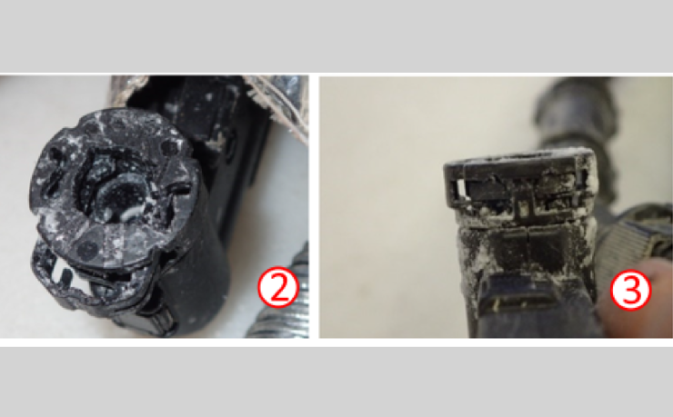
Fig. 3
TIP: The cleaning procedure cannot be performed if the Emission Reduction Fluid Exhaust Front Pipe Injector Supply Pipe connector is contaminated with other forms of contaminants, such as frame wax or dirt inside the connector. (Fig. 4) If these types of contaminants are present, the Emission Reduction Fluid Exhaust Front Pipe Injector Supply Pipe will need to be replaced.
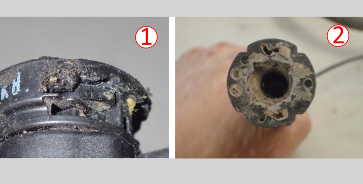
Fig. 4
The cleaning procedure will help remove any DEF crystallization contamination within the connector interface of the supply pipe. To disconnect the supply pipe connector, depress the tab while pushing the female side towards the male connector. (Fig. 5)
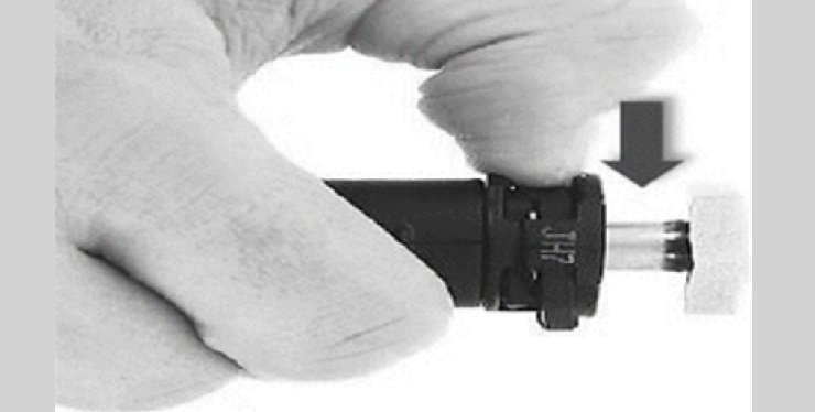
Fig. 5
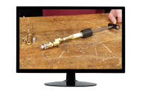
The cleaning procedure includes disconnecting the Emission Reduction Fluid Exhaust Front Pipe Injector Supply Pipe connector from the Reductant Fluid Injector or the Emission Reduction Fluid Pump Outlet Port (detach any clips or liners as needed for access), wiping off any dust or dirt present on the outside of the connector, and then submerging the Emission Reduction Fluid Exhaust Front Pipe Injector Supply Pipe connector end into a container filled with clean water. With the open end of the connector facing up, the connector should be submerged in the water for one minute and then swished around in the water for another minute to help dislodge any crystals embedded inside the connector. (Fig. 6) Refer to Bulletin #24-NA-020 for complete cleaning instructions.
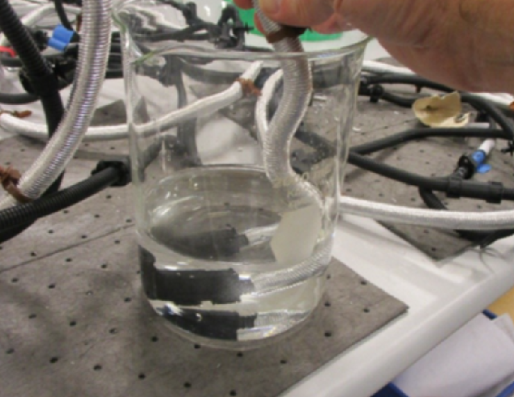
Fig. 6
If the Reductant Fluid Injector side of the Emission Reduction Fluid Exhaust Front Pipe Injector Supply Pipe is disconnected, also command the Reductant Pump at 50% duty cycle with the connector in the container to clean any contamination within the connector interface.
Inspect the Emission Reduction Fluid Exhaust Front Pipe Injector Supply Pipe connector end for any remaining crystallization and repeat the cleaning steps if needed.
When reinstalling the connector, there may be a locking tab that pops up. Activate the locking tab by pressing down on the tab and applying pressure towards the male connector. Once latched, check for a secure connection by pulling outward on the female connector.
Refer to Bulletin #24-NA-020 for additional information.
– Thanks to Dave MacGills, Kevin Minor and Mike Wasczcenko


